background image

ELAD FDM-DUOr 


User Manual - Rev. 1.1 - 04/2016 


© 2016 ELAD S.r.l. All rights reserved. No part of this document may be reproduced, published, used, disclosed or disseminated in any form or 

by any means, electronic, photocopying or otherwise, without prior written permission of ELAD S.r.l.


35 

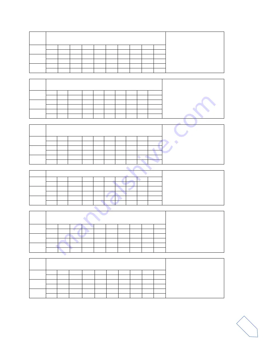
NB 

Reads the noise blanker function status 
 

Parameters: 

 P1 
  0: Noise Blanker OFF 
  1: Noise Blanker ON


Set 


Read 

1


2


3


4


5


6


7


8


9


10


Answer 

1


2


3


4


5


6


7


8


9


10


P1 


NC 

Reads or sets the noise reduction value 


Parameters: 
 P1 always  0 
 
 P2 noise reduction value 
  0: OFF 
  01 ~ 10 (active) 
 

Set 

10 

P1 

P2  P2  P2 


Read 

10 

P1 


Answer 

10 

P1 

P2  P2  P2 


NK 

Reads or sets the noise blanker value 


Parameters: 
P1 always  0 
 
P2 noise blanker value 
  0: OFF 
  01 ~ 10 (active) 
 

Set 

10 

P1 

P2  P2  P2 


Read 

10 

P1 


Answer 

10 

P1 

P2  P2  P2 


NO 

Reads or sets the auto notch value


Parameters: 
P1 always  0 
 
P2 auto notch value 
  0: OFF 
  01 ~ 02 (active) 
 

Set 

10 

P1 

P2  P2  P2 


Read 

10 

P1 


Answer 

10 

P1 

P2  P2  P2 


NR 

Reads the noise reduction function status 
 

Parameters: 
P1 
 

0: Noise Reduction OFF 

 1: Noise Reduction ON


Set 


Read 

1


2


3


4


5


6


7


8


9


10


Answer 

1


2


3


4


5


6


7


8


9


10


P1 


OS 

Sets/Reads the Frequency view offset status 


Parameters: 
P1  
   0: not active 
   1: active 

Set 

10 

P1 


Read 

1


2


3


4


5


6


7


8


9


10


Answer 

1


2


3


4


5


6


7


8


9


10


P1 


Summary of Contents for FDM-DUOr

Page 1: ...www eladit com ELAD FDM DUOr Dual Mode SDR Receiver USER MANUAL...

Page 2: ...gram 6 1 4 Precautions 7 2 Panels Description 8 2 1 Front Panel Description 8 2 2 Rear Panel Description 9 2 3 Preselectors Description 11 2 3 1 Preselectors Slots 11 2 3 2 Preselectors List 12 3 LCD...

Page 3: ...8 6 2 Commands Types 28 6 3 Cat Commands 29 6 3 1 Active commands list 29 6 3 2 Active commands tables 30 6 3 3 Compatibility commands 41 7 Software Driver Installation 47 7 1 Software installation 47...

Page 4: ...isclosed or disseminated in any form or by any means electronic photocopying or otherwise without prior written permission of ELAD S r l 4 Revision History Revision Date Description Rev 1 1 04 2016 Ad...

Page 5: ...covering the frequency range from 9kHz to 54MHz The FDM DUOr can be used like a standard receiver in stand alone mode or in remote mode to exploit the full potential of the ELAD FDM SW2 software The...

Page 6: ...LAD S r l All rights reserved No part of this document may be reproduced published used disclosed or disseminated in any form or by any means electronic photocopying or otherwise without prior written...

Page 7: ...t the receiver only to a power source described in this manual Take care when plugging in cables avoid applying sideways pressure that might damage the connectors Avoid operating in wet conditions For...

Page 8: ...or more information about knobs use 3 Main Knob Available functions VFO tuning memory selection in MEM mode step selection in VFO mode See Knobs functions for more information about knobs use 4 Main a...

Page 9: ...port Connect it to computer to use the SW2 software Please use the supplied cable 2 Frequency Reference Input SMA 50 Ohm connector Apply an 10MHz 0dBm signal 3 Input Antenna 1 Connector M type 50 Ohm...

Page 10: ...r through the CAT Computer Aided Transceiver protocol 7 Power Switch Turns on or off the FDM DUOr 8 Power Connector Voltage to apply 13 8V Maximum current consumption 0 6A DC 9 Expansion Port DB9 conn...

Page 11: ...of ELAD S r l 11 2 3 Preselectors Description 2 3 1 Preselectors Slots The FDM DUOr has ten slots for preselector filters To change the preselectors configuration remove the top cover identify the app...

Page 12: ...e preselectors Code Description Code Description FHP05M 1 High Pass 500 kHz FBP17 1 Band Pass 17 m FHP1M7 1 High Pass 1700 kHz FBP15 1 Band Pass 15 m FBP160 1 Band Pass 160 m FBP12 1 Band Pass 12 m FB...

Page 13: ...ate that the QuickStep function is active 4 PK blinks if the ADC of reception is overloaded 5 Secondary indication displays the signal strength in dBm 6 Measurement unit for the secondary indication 7...

Page 14: ...n VOL main volume setting SQL squelch setting for FM mode AGC automatic gain control settings NR noise reduction setting NB noise blanker setting AN auto notch setting 14 Displays the selected VFO A o...

Page 15: ...white label is associated to the short pressure on the button while the lower blue label is associated to the long pressure The knobs can be pressed as well to control a different parameter swaps A a...

Page 16: ...ry settings 4 3 A first trip A radio like FDM DUOr has many possible application scenarios both used as a stand alone device and paired with its mate software In this section the simplest and most com...

Page 17: ...resets the usual tuning step It is possible to change the tuning step to various values with a short pressure on the tuning knob This leads the tuning knob to select different tuning steps Once the de...

Page 18: ...5 Noise Reduction it is possible to activate and set the level if activated the NR icon on the display blinks 6 Noise Blanker it is possible to activate and set the level if activated the NB icon on...

Page 19: ...FO memorize the tuning frequency mode and tuning step 5 1 1 Tuning In this mode use the Main Knob to tune a frequency A short pressure on the main knob enter the frequency step menu Use the main knob...

Page 20: ...icon blinks NR and NB if the Noise Reducer or the Noise Blanker is turned on the relative NR or NB icon blinks 5 1 3 E2 Receiver Settings Apply a short pressure on the E2 knob to change the E2 selecte...

Page 21: ...pears on the LCD display then release the key and the current VFO is set to the frequency and mode saved in the memory channel You can use the FDM DUOr Manager feature in the ELAD FDM SW2 software to...

Page 22: ...ame way of the VFO mode 5 2 1 Select and edit a memory Use the main knob to select a memory Apply a long pressure on the main encoder to enter the edit memory menu In this menu it is possible to modif...

Page 23: ...ny means electronic photocopying or otherwise without prior written permission of ELAD S r l 23 5 2 4 Change the memory display mode Apply a short pressure on the key to show the memory label in the L...

Page 24: ...election parameter Short Pressure Change E1 selected parameter Change E2 selected parameter Long Pressure Switch to DIGIT by DIGIT tuning mode 2 2 E1 Selection VOL SQL AGC NR NB Value modified Back to...

Page 25: ...hort Pressure Switch to standard tuning mode Switch to standard tuning mode Switch to standard tuning mode Long Pressure 2 2 1 Available only for certain menu 2 Press simultaneously E1 and E2 to lock...

Page 26: ...0Hz 25Hz 50Hz 100Hz 250Hz 500Hz 1kHz 2kHz 3kHz 4 5kHz 5kHz 7 5kHz 9kHz 10kHz 12 5kHz 25kHz 50kHz 100kHz 125kHz 250kHz 500kHz 1MHz 1kHz 12 SET CW MODE Enable disable CW reverse mode YES or NO NO GENERA...

Page 27: ...g a transverter The Frequency offset set in digit by digit mode with some improvements to set a signed 10 digit offset in a 9 digit display E2 Select the digit to modify Main encoder modify the select...

Page 28: ...uxe 6 2 Commands Types A CAT command is composed of an alphabetical part various parameters and a terminator that signals the end of the command For example to set the VFO A to 14MHz the command is FA...

Page 29: ...YES YES YES MA VFO A MODE YES YES MB VFO B MODE YES YES MC MEMORY CHANNEL YES YES YES MD MODE YES YES YES MR MEMORY READ YES YES MU MUTE RX YES YES YES MW MEMORY WRITE YES NB NOISE BLANKER STATUS YES...

Page 30: ...e FDM DUO type Parameters P1 Always 002 Set Read 1 2 3 4 5 6 7 8 9 10 D T Answer 1 2 3 4 5 6 7 8 9 10 D T P1 P1 P1 FA Reads or sets the VFO A frequency Parameters P1 Frequency in Hz 11 digit Set 1 2 3...

Page 31: ...P4 21 22 23 24 25 26 27 28 P4 P4 P4 P4 P4 P4 P4 Read 1 2 3 4 5 6 7 8 9 10 F I P1 P1 Answer 1 2 3 4 5 6 7 8 9 10 F I P1 P1 P2 P3 P3 P3 P3 P3 11 12 13 14 15 16 17 18 19 20 P3 P3 P3 P3 P3 P3 P4 P4 P4 P4...

Page 32: ...Reads or sets the control gain settings Parameters P1 0 auto AGC 1 manual P2 for P1 0 0 slow 1 medium 2 fast P2 for P1 1 0 OFF 1 a 10 active Set 1 2 3 4 5 6 7 8 9 10 G S P1 P2 P2 P2 Read 1 2 3 4 5 6...

Page 33: ...P4 P5 11 12 13 14 15 16 17 18 19 20 P5 P5 Read 1 2 3 4 5 6 7 8 9 10 L B P2 Answer 1 2 3 4 5 6 7 8 9 10 L B P2 P3 P3 P3 P4 P4 P4 P5 11 12 13 14 15 16 17 18 19 20 P5 P5 MA Reads the VFO A operating mod...

Page 34: ...P4 P4 P4 P4 P5 P6 P7 21 22 23 24 25 26 27 28 29 30 P8 P8 P9 P9 P10 P10 P10 P10 P10 P10 31 32 33 34 35 36 37 38 39 40 P10 P10 P10 P10 P10 P10 P10 P10 P11 P12 41 42 43 44 45 46 47 48 49 50 P15 P16 P16 P...

Page 35: ...r 1 2 3 4 5 6 7 8 9 10 N C P1 P2 P2 P2 NK Reads or sets the noise blanker value Parameters P1 always 0 P2 noise blanker value 0 OFF 01 10 active Set 1 2 3 4 5 6 7 8 9 10 N K P1 P2 P2 P2 Read 1 2 3 4 5...

Page 36: ...3 P3 P3 P3 OW Sets Reads the Frequency view offset value Parameters P1 Offset sign P2 Absolute value in Hz Set 1 2 3 4 5 6 7 8 9 10 O W P1 P2 P2 P2 P2 P2 P2 P2 11 12 13 14 15 16 17 18 19 20 P2 P2 P2 P...

Page 37: ...9 10 R D P2 RF Reads or sets the reception filters values Parameters P1 like MD command 1 LSB 2 USB 3 7 CW CWR 4 FM 5 AM P2 see parameter details below Set 1 2 3 4 5 6 7 8 9 10 R F P1 P2 P2 Read 1 2...

Page 38: ...r 1 2 3 4 5 6 7 8 9 10 R T P1 RU Sets RIT to a positive value Parameters P1 positive value of RIT to set from 0 to 50000Hz max value subject to change P2 always 1 Set 1 2 3 4 5 6 7 8 9 10 R U P1 P1 P1...

Page 39: ...3 4 5 6 7 8 9 10 Read 1 2 3 4 5 6 7 8 9 10 S M P1 Answer 1 2 3 4 5 6 7 8 9 10 S M P1 P2 P2 P2 P2 SN Reads the receiver serial number Parameters P1 Serial number Set 1 2 3 4 5 6 7 8 9 10 Read 1 2 3 4 5...

Page 40: ...Reads or sets the main volume Parameters P1 000 005 010 100 in 5 dots step Set 1 2 3 4 5 6 7 8 9 10 V M P1 P1 P1 Read 1 2 3 4 5 6 7 8 9 10 V M Answer 1 2 3 4 5 6 7 8 9 10 V M P1 P1 P1 VS Reads the FDM...

Page 41: ...Read 1 2 3 4 5 6 7 8 9 10 A C Answer 1 2 3 4 5 6 7 8 9 10 A C P1 P1 P2 AG Parameters P1 Always 0 P2 Always 000 Set 1 2 3 4 5 6 7 8 9 10 Read 1 2 3 4 5 6 7 8 9 10 A G P1 Answer 1 2 3 4 5 6 7 8 9 10 A...

Page 42: ...8 9 10 C N Answer 1 2 3 4 5 6 7 8 9 10 C A P1 P1 CT Parameters P1 Always 0 Set 1 2 3 4 5 6 7 8 9 10 Read 1 2 3 4 5 6 7 8 9 10 C T Answer 1 2 3 4 5 6 7 8 9 10 C T P1 DL Parameters P1 Always 0 P2 Alway...

Page 43: ...4 5 6 7 8 9 10 G T Answer 1 2 3 4 5 6 7 8 9 10 G T P1 P1 P1 ID Parameters P1 020 Set 1 2 3 4 5 6 7 8 9 10 Read 1 2 3 4 5 6 7 8 9 10 I D Answer 1 2 3 4 5 6 7 8 9 10 I D P1 P1 P1 IS Parameters P1 P2 Al...

Page 44: ...6 7 8 9 10 P A Answer 1 2 3 4 5 6 7 8 9 10 P A P1 P2 PC Parameters P1 Always 005 Set 1 2 3 4 5 6 7 8 9 10 Read 1 2 3 4 5 6 7 8 9 10 P C Answer 1 2 3 4 5 6 7 8 9 10 P C P1 P1 P1 PR Parameters P1 Always...

Page 45: ...er 1 2 3 4 5 6 7 8 9 10 R L P1 P1 RM Parameters P1 Always 1 P2 Always 0001 Set 1 2 3 4 5 6 7 8 9 10 Read 1 2 3 4 5 6 7 8 9 10 R M Answer 1 2 3 4 5 6 7 8 9 10 R M P1 P2 P2 P2 P2 SD Parameters P1 Always...

Page 46: ...O Parameters P1 Always 0 Set 1 2 3 4 5 6 7 8 9 10 Read 1 2 3 4 5 6 7 8 9 10 T O Answer 1 2 3 4 5 6 7 8 9 10 T O P1 TS Parameters P1 Always 0 Set 1 2 3 4 5 6 7 8 9 10 Read 1 2 3 4 5 6 7 8 9 10 T S Answ...

Page 47: ...ise without prior written permission of ELAD S r l 47 7 Software Driver Installation 7 1 Software installation 7 1 1 First time install in Windows 8 and Windows 7 Double click the file setup exe in th...

Page 48: ...rights reserved No part of this document may be reproduced published used disclosed or disseminated in any form or by any means electronic photocopying or otherwise without prior written permission of...

Page 49: ...ublished used disclosed or disseminated in any form or by any means electronic photocopying or otherwise without prior written permission of ELAD S r l 49 Microsoft Visual C 2010 x86 Redistributable i...

Page 50: ...is document may be reproduced published used disclosed or disseminated in any form or by any means electronic photocopying or otherwise without prior written permission of ELAD S r l 50 Click to Next...

Page 51: ...S r l All rights reserved No part of this document may be reproduced published used disclosed or disseminated in any form or by any means electronic photocopying or otherwise without prior written per...

Page 52: ...ocument may be reproduced published used disclosed or disseminated in any form or by any means electronic photocopying or otherwise without prior written permission of ELAD S r l 52 7 1 2 First time i...

Page 53: ...l All rights reserved No part of this document may be reproduced published used disclosed or disseminated in any form or by any means electronic photocopying or otherwise without prior written permis...

Page 54: ...of this document may be reproduced published used disclosed or disseminated in any form or by any means electronic photocopying or otherwise without prior written permission of ELAD S r l 54 Click on...

Page 55: ...reserved No part of this document may be reproduced published used disclosed or disseminated in any form or by any means electronic photocopying or otherwise without prior written permission of ELAD S...

Page 56: ...be reproduced published used disclosed or disseminated in any form or by any means electronic photocopying or otherwise without prior written permission of ELAD S r l 56 7 1 3 Update an existing softw...

Page 57: ...SB driver 7 2 1 USB driver installation in Windows 8 and Windows 7 7 2 1 1 First driver installation To install ELAD FDM DUOr driver connect the FDM DUOr USB RX port to a USB 2 0 socket on PC end powe...

Page 58: ...indows starts the installation procedure select the option Browse my computer for driver software the second option In the next dialog box insert the driver folder location using Browse button and che...

Page 59: ...r disseminated in any form or by any means electronic photocopying or otherwise without prior written permission of ELAD S r l 59 Let the hardware installation automatically completes and at the proce...

Page 60: ...stallation verify To verify FDM DUO driver current version connect the device to USB socket where the device driver is already installed and power on the device Then open Control Panel from Start menu...

Page 61: ...n of ELAD S r l 61 7 2 1 3 Manual driver update To update FDM DUO driver connect the device to USB RX socket where the device driver is already installed and power on the device Then open Control Pane...

Page 62: ...LAD S r l 62 In the next dialog box disable the option Include subfolders and choose Let me pick from a list of device drivers on my computer Don t click Next Verify that Show compatible hardware opti...

Page 63: ...ware installation automatically completes and at the procedure ending click on Close then disconnect and connect FDM DUOr device on the same USB socket To verify that a correct update is done enter De...

Page 64: ...USB 2 0 socket on PC and power on the device Windows XP detects the new hardware and starts the hardware installation wizard Then next steps to install FDM DUOr driver are listed below At the first d...

Page 65: ...ed disclosed or disseminated in any form or by any means electronic photocopying or otherwise without prior written permission of ELAD S r l 65 Let the hardware installation automatically completes an...

Page 66: ...verify To verify FDM DUOr driver current version connect the device to USB socket where the device driver is already installed and open Control Panel from Start menu Click on System and select Device...

Page 67: ...ELAD S r l 67 7 2 2 3 Manual driver update To update FDM DUOr driver connect the device to USB socket where the device driver is already installed and power on the device Then open Control Panel from...

Page 68: ...otherwise without prior written permission of ELAD S r l 68 At next step select Install from a list or specific location Advanced and Next Then disable all check boxes that the system automatically s...

Page 69: ...written permission of ELAD S r l 69 Click on Browse and search for the FDM DUOr driver update folder location then open winusb_fdmsampler inf file as depicted in figure Click OK and then Next Now dri...

Page 70: ...c photocopying or otherwise without prior written permission of ELAD S r l 70 To verify that a correct update is done enter Device Manager from Control Panel under ELAD Samplers list select ELAD FDM D...

Page 71: ...electronic photocopying or otherwise without prior written permission of ELAD S r l 71 7 2 3 USB CAT Serial port Connect the CAT USB port of FDM DUOr to a USB 2 0 port of the PC Windows download and...

Page 72: ...section describes how to update the various firmware of the FDM DUO The latest firmware versions are available here http sdr eladit com FDM DUO Firmware Releases TO FACILITATE THE PROCEDURE PLEASE UPD...

Page 73: ...t be in the root of the USB flash drive For example E fdmduorx bin Connect the provided USB flash drive to the FDM DUOr RX USB PROGRAMMING PORT using the provided micro USB adapter See the picture bel...

Page 74: ...and connect the USB RX connector to a USB 2 0 port of your computer Unzip the archive launch the executable file inside and follow the instructions to update the firmware Do not disconnect the USB cab...

Page 75: ...firmware you need to install the Flash Magic software This program is available here http www flashmagictool com Turn on the FDM DUOr and connect the CAT USB port to a USB 2 0 port of your computer F...

Page 76: ...2 Erase section Check Erase all Flash Code Rd Prot In the Step 3 Hex File section Click on Browse and select the update hex file In the Step 4 Options section Check Verify after programming 0 Check t...

Page 77: ...S r l All rights reserved No part of this document may be reproduced published used disclosed or disseminated in any form or by any means electronic photocopying or otherwise without prior written per...

Page 78: ...d in conformity to the requirements contained in the following EC directives R TTE Directive 1999 5 CE EMC Directive 2004 108 CE Low Voltage Directive 2006 95 CE RoHS Directive 2011 65 CE The product...

Reviews: