INSTRUCTION MANUAL
This device complies with Part 15 of the FCC rules. Operation is subject to the condition that this device does not cause harmful interference.
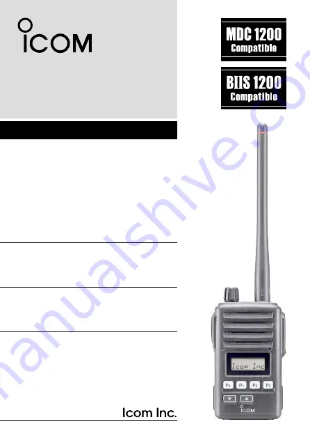
UHF TRANSCEIVER
iF60
VHF TRANSCEIVER
iF50
Page 1: ...NSTRUCTION MANUAL This device complies with Part 15 of the FCC rules Operation is subject to the condition that this device does not cause harmful interference UHF TRANSCEIVER iF60 VHF TRANSCEIVER iF5...
Page 2: ...nt C Evaluating Com pliance with FCC Guidelines for Human Exposure to Radio Fre quency Electromagnetic Fields American National Standards Institute C95 1 1992 IEEE Standard for Safety Levels with Resp...
Page 3: ...ments are not exceeded To provide the recipients of your transmission the best sound quality hold the antenna at least 5 cm 2 inches from your mouth and slightly off to one side The information listed...
Page 4: ...ur NOTE If disregarded inconvenience only No risk of personal injury fire or electric shock OPERATING NOTES When transmitting with a portable radio hold the radio in a vertical position with its micro...
Page 5: ...on will ruin the transceiver DO NOT push the PTT when not actually desiring to transmit DO NOT use or place the transceiver in direct sunlight or in areas with temperatures below 30 C 22 F or above 60...
Page 6: ...er ON 12 Channel selection 12 Call procedure 13 Receiving and transmitting 14 Scrambler function 17 User Set mode 18 4 BIIS OPERATION 19 33 Default setting 19 Receiving a call 20 Transmitting a call 2...
Page 7: ...erial number seal con form to intrinsically safe ratings of the FMRC Factory Mutual Research Corporation Intrinsically safe Class I II III Division 1 Groups C D E F G Nonincendive Class I Division 2 G...
Page 8: ...ion of the arrow q then lock it with the battery release button Slide the battery pack until the battery release button makes a click sound To remove the battery pack Push the battery release button i...
Page 9: ...er q Insert the jack cover into the SP MIC connector w Tighten the screw To detach the jack cover e Remove the screw with a phillips screwdriver r Detach the jack cover for the speaker microphone con...
Page 10: ...or dust proofing becomes wet dry it with a hair drier cool mode etc before operating the transceiver Otherwise the audio may be difficult to hear for loss of the sound pressure q VOLUME CONTROL VOL Tu...
Page 11: ...andby condition push to select an operating channel After pushing TX Code CH Select push to select a TX code channel After pushing DTMF Autodial push to select a DTMF channel After pushing and holding...
Page 12: ...hen the compander function is activated r KEY LOCK INDICATOR Appears during the key lock function ON t SCRAMBLER INDICATOR Appears when the voice scrambler function is activated y BELL INDICATOR Appea...
Page 13: ...MF channel after pushing the DTMF Autodial key Select a scan group after pushing and holding the Scan A Start Stop Scan B Start Stop keys Select a BIIS code status number or SDM after pushing the Digi...
Page 14: ...to un mute the channel audio is emitted Audible condition Push to mute the channel sets to Inaudible only Push to un mute the channel sets to Audible only Push after the communication is finished to s...
Page 15: ...from 25 0 or 20 0 kHz using the CS F50 cloning software PMR or BIIS PMR operation only Ask your dealer for details DTMF AUTODIAL KEY Push to enter the DTMF channel selection mode Then select the desi...
Page 16: ...t mode for both 5 tone and MSK Then set the desired digit using CH Up CH Down TX Code CH Up TX Code CH Down p 16 TX CODE CHANNEL SELECT KEY Push to enter the direct ID code channel selection mode Then...
Page 17: ...h and hold this key again to exit the User Set mode DIGITAL KEY BIIS operation only Push to select the call ID list transmit message and standby condition Toggles between queue channel and received me...
Page 18: ...sh to return to the MDC menu selection mode MDC UP AND DOWN KEYS MDC operation only Push to select the MDC menu after pushing MDC CALL Push to select the desired transceiver alias or message chan nel...
Page 19: ...lear after inputting 4 digits the input code number may be incorrect Turn the power off and start over in this case Channel selection Several types of channel selections are available Methods may dif...
Page 20: ...tation s only and prevent unwanted stations from contacting you q Select the desired TX code channel or 2 5 tone code according to your System Operator s instructions This may not be necessary dependi...
Page 21: ...stening level Transmitting Wait for the channel to become clear to avoid interference q While pushing and holding PTT speak into the microphone at a normal voice level When a tone signalling system is...
Page 22: ...further inhib ited for a period determined by the penalty timer D TX code channel selection If the transceiver has TX Code CH Select assigned to it indication can be toggled between the operating cha...
Page 23: ...ired digit using TX Code CH Up TX Code CH Down t Push TX Code CH Select to set the digit The editable digit will move to the right automatically y Repeat r and t to input all allowable digits u Push C...
Page 24: ...h to select the desired DTMF channel e Push DTMF Autodial to transmit the DTMF code in the selected DTMF channel Scrambler function The voice scrambler function provides private communication between...
Page 25: ...sh and hold User Set Mode for 1 sec to enter the User Set mode w Push User Set Mode momentarily to select the appropriate item Then push CH Up or CH Down to set the desired level condition In the User...
Page 26: ...respectively P1 Digital Push to select the call list ID transmit mes sage or to display the receive message re cord for selection P3 Moni Audi Push this key after the communication to send a clear dow...
Page 27: ...ending on the setting Appears or blinks Appears w Push and hold PTT then speak into the microphone at a nor mal voice level Transmit Busy indicator lights red e Release PTT to return to receive Transm...
Page 28: ...ks Appears w Push and hold PTT then speak into the microphone at a nor mal voice level NOTE Only one station is permitted to speak Transmit Busy indicator lights red e Release PTT to return to receive...
Page 29: ...th call is received However once the transceiver is pow ered OFF the all records are cleared q Push P1 Digital for 1 sec Displays following indication When a record is available When no record is avai...
Page 30: ...ory channel selection mode Call code text is displayed w Push to select the desired call code e Push P0 Call or PTT to call PTT call can be made only when PTT call capability is permitted NOTE When no...
Page 31: ...P0 Call or PTT to call PTT call can be made only when PTT call capability is permitted NOTE When no answer back is received the transceiver re peats the call 3 times default automatically and is displ...
Page 32: ...tomatically t Repeat e and r to input all allowable digits y Push P0 Call or PTT to call PTT call can be made only when PTT call capability is permitted NOTE When no answer back is received the transc...
Page 33: ...or text and the status message is displayed alternately depending on the setting w Push P3 Moni Audi to return to the standby condition NOTE Only the calling station ID or text is displayed no message...
Page 34: ...the SDM is displayed alternately depending on the setting w When the received SDM includes more than 8 characters the message scrolls automatically when the automatic scroll func tion is activated Pu...
Page 35: ...Displays queue memory w Push P1 Digital momentarily Displays message memory When a message is available When no message is available e Push to select the desired message When selecting the SDM that in...
Page 36: ...24 is fixed The status call can be sent with both individual and group calls D Transmitting a status q While in the standby condition push P1 Digital then push to select the desired station group cod...
Page 37: ...push P1 Digital then push to select the desired station group code w Push P1 Digital again then push to select the desired SDM Or you can select the desired SDM using Status Up Status Down key direct...
Page 38: ...transmission is enabled send the po sition data according to Time Marker and Interval Timer set tings PTT is released When Send with Logoff is enabled Set the Log In Off item as L OFF After sending a...
Page 39: ...e tone func tion can be used to inform you that the ID is sent and voice com munication can be performed Auto emergency transmission When Emergency Single Silent or Emergency Repeat Silent is pushed a...
Page 40: ...M transmission is successful No answer back is received Appears during retry of the call 2nd call End the communication Operating channel is in the busy condition Priority A channel selection When one...
Page 41: ...he system An additional feature of MDC 1200 found in Icom transceivers is called aliasing Each transceiver on the system has a unique ID number Aliasing allows the substitution of an alphanumeric name...
Page 42: ...tion or group ID s q Push MDC Call to enter the MDC menu selection mode Or push MDC Selcall to enter the transceiver alias selection mode In this case skip step w w Push MDC Call again to enter the tr...
Page 43: ...w Select CALALERT using CH Up CH Down MDC Up or MDC Down e Push MDC Call again to enter the transceiver alias selection mode r Select the desired alias using CH Up CH Down MDC Up or MDC Down t Push PT...
Page 44: ...CH Down MDC Up or MDC Down e Push MDC Call again to enter the transceiver alias selection mode r Select the desired alias using CH Up CH Down MDC Up or MDC Down t Push PTT to transmit the radio check...
Page 45: ...the MDC menu selection mode w Select STATUS using CH Up CH Down MDC Up or MDC Down e Push MDC Call again to enter the status message selection mode Pre programmed status message is displayed r Select...
Page 46: ...DC Up or MDC Down e Push MDC Call again to enter the pre programmed message selection mode Pre programmed message is displayed r Select the desired message using CH Up CH Down MDC Up or MDC Down t Pus...
Page 47: ...CD indication change depends on the setting With MDC 1200 Emergency the transceiver can also be pro grammed to keep the microphone open during an emergency call allowing monitoring of the situation As...
Page 48: ...LCALL are displayed alternately Appears Blinks w Push and hold PTT and speak into the microphone e Release PTT to receive a response D Receiving a Call Alert q When a Call Alert is received Beeps soun...
Page 49: ...Receiving an Emergency Call q When an emergency call is received Beeps sound The calling station ID or alias and EMG EMG are displayed al ternately w Turn power OFF change the channel etc to stop the...
Page 50: ...re range for charging BC 190 BC 119N BC 121N 10 C to 40 C 50 F to 104 F BC 152N 0 C to 45 C 32 F to 113 F The Li ion battery 0 C to 45 C 32 F to 113 F The Li ion battery functions within 10 C to 60 C...
Page 51: ...ter can easily get into it R DANGER NEVER immerse the battery pack in water If the battery pack becomes wet be sure to wipe it dry immediately par ticularly the battery terminals BEFORE attaching it t...
Page 52: ...arger The charge indicator lights orange r Charge the battery pack approximately 10 hours depending on the remaining power condition The charge indicator lights green when charging is completed Charge...
Page 53: ...n then reinsert it If you are unable to solve the problem through the use of these solutions the battery pack or the charger may be damaged or the battery life may be over In that case contact your ne...
Page 54: ...ack approximately 2 5 to 4 25 hours de pending on the remaining power condition and whether the transceiver s power is ON OFF The charge indicator lights green when charging is completed AC adapter A...
Page 55: ...or BC 121N before battery charging q Attach the plugs from the BC 119N BC 121N to the AD 100 charger adapter w Secure the AD 100 into the holder space of the BC 119N BC 121N with the supplied screws A...
Page 56: ...harger adapter is installed in BC 119N Battery pack Turn power OFF Transceiver Optional OPC 515L for 13 8 V power source or CP 23L for 12 V cigarette lighter socket can be used instead of the AC adapt...
Page 57: ...pack See the instruction manual for details of the charger LED indication operation etc Transceiver Turn power OFF AD 100 charger adapters are installed in each slot CAUTION NEVER connect the OPC 656...
Page 58: ...tteries Leave enough of the ribbon ends extended to pull when removing the batteries e Close the cover by fitting in the direction of the arrow w first then check the latch is in place e Fig 1 Be sure...
Page 59: ...52 6 BATTERY CHARGING 6 q w e BP 226 Latch Fig 1 Fig 2 Ribbon Fig 3 Gasket Ribbon...
Page 60: ...aker NEVER immerse the connector in water If the connector becomes wet be sure to dry it BEFORE attaching it to the transceiver NOTE The microphone is located at the top of the speaker mi crophone as...
Page 61: ...cover attached trans ceiver when the speaker microphone is not in use Water will not get into the transceiver even if the cover is not attached however the terminals pins will become rusty or the tran...
Page 62: ...ter BC 145 is not supplied with some versions Charging time Approximately 2 5 to 4 25 hours for BP 227 FM BC 119N desktop charger AD 100 charger adapter BC 145S ac adapter Used for rapid charging of b...
Page 63: ...orre sponds to IPX7 Once these items have been dropped the IP rating or waterproof protection can not be guaranteed because of possible damage to these cases or the waterproof seals OPC 966 interface...
Page 64: ...1 1 32 Kamiminami Hirano ku Osaka 547 0003 Japan A 6533H 1EX t Printed in Japan 2006 2012 Icom Inc Printed on recycled paper with soy ink...