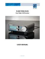
ELAD FDM-DUOr
User Manual - Rev. 1.1 - 04/2016
© 2016 ELAD S.r.l. All rights reserved. No part of this document may be reproduced, published, used, disclosed or disseminated in any form or
by any means, electronic, photocopying or otherwise, without prior written permission of ELAD S.r.l.
10
6 - CAT USB Serial Port
USB 2.0 port. Connect it to the computer to manage the FDM-DUOr through the CAT (Computer Aided
Transceiver) protocol.
7 - Power Switch
Turns on or off the FDM-DUOr.
8 - Power Connector
Voltage to apply : 13.8V. Maximum current consumption : 0.6A DC.
9 - Expansion Port
DB9 connector for external hardware.
THIS IS NOT A STANDARD SERIAL PORT.
Pin 1: SPI Latch
Pin 2: I2C SCL
Pin 3: SPI Clock
Pin 4: I2C SDA
Pin 5: Ground
Pin 6: DUOr TX
Pin 7: DUOr RX
Pin 8: SPI Data
Pin 9: +5V
10 – Main audio output for speakers and headphones (rear panel)
11 – Ground Connector
For better performance and safety, connect it to an earth ground using a short and wide cable.


