background image

24

Italiano

Français

English

OPERAZIONI PRELIMINARI

PREPARATION

PREPARING TO WORK

40

41

42

43

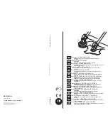
CORRETTA REGOLAZIONE DEL CINGHIAGGIO 
dei modelli “TWIN”
1.  Indossare il cinghiaggio di tipo doppio (Fig.40).
2.  Agganciare la fi bbia (A, Fig.41) in zona cintura e regolarla agendo sulla 

cinghia superiore (B).

3.  Agganciare la fi bbia (C) in zona torace.
4.  Regolare le spalline con le due cinghie (D, Fig.42). Con questo cinghiaggio 

è possibile distribuire il carico maggiormente sulle spalle o in cintura a 
discrezione dell’operatore.

5.  Regolare la cinghia (E, Fig.41) zona torace.
6.  Agganciare il decespugliatore al cinghiaggio tramite il moschettone (F, 

Fig.43).

7. Posizionare il gancio (G) per ottenere il miglior bilanciamento del 

decespugliatore.

8.  Regolare l’altezza della macchina dal terreno agendo sulle due cinghie (H-

L, Fig.44). La corretta distanza tra la cintura ed il moschettone (F, Fig.43), 
può essere misurata come in Fig.45. Questa regolazione favorisce inoltre 
la ripartizione corretta del peso per ottenere un buon bilanciamento del 
decespugliatore.

ATTENZIONE! - Nel caso di utilizzo di lame da legno (22-60-80 denti) 

è obbligatorio l’utilizzo di un cinghiaggio doppio dotato di sgancio rapido.

CINGHIAGGIO MODELLI "IC"
Una corretta regolazione del cinghiaggio permette al decespugliatore di avere 
un buon bilanciamento ed una adatta altezza dal terreno (Fig. 45).
-  Indossare il cinghiaggio di tipo semplice.
-  Agganciare il decespugliatore al cinghiaggio tramite il moschettone (A, Fig. 

47)

- Posizionare il gancio (B) per ottenere il miglior bilanciamento del 

decespugliatore.

- Posizionare   la   fi bia   (C)   per   ottenere   la corretta altezza del 

decespugliatore.

NORME D'USO
-  Indossare il cinghiaggio e tenere sempre entrambe le mani sulle impugnature 

durante il funzionamento del decespugliatore.

-  Utilizzare il decespugliatore come illustrato in Fig. 46.
- Verifi care sempre che il disco non subisca incrinature dopo urti accidentali 

contro oggetti estranei (sassi, ecc.).

RÉGLAGE CORRECT DU HARNAIS modeles “TWIN”
1.  Porter le harnais double (Fig.40).
2.  Attacher la boucle (A, Fig.41) de la ceinture et la régler en agissant sur la 

courroie supérieure (B).

3.  Attacher la boucle (C) sur le thorax.
4.  Régler les épaules avec les deux courroies (D, Fig.42). Ce harnais permet de 

répartir la charge davantage sur les épaules ou au niveau de la ceinture, comme 
le préfère l’opérateur.

5.  Régler la courroie (E, Fig.41) au niveau du thorax.
6.  Accrocher la débroussailleuse à l’aide du mousqueton (F, Fig.43).
7.  Placer le crochet (G) de sorte à équilibrer la débroussailleuse.
8.  Régler la hauteur de l’appareil par rapport au sol en agissant sur les deux courroies 

(H-L, Fig.44). La fi gure 45 illustre comment régler correctement la distance 
entre la ceinture et le mousqueton (F, Fig.43). Ce réglage facilite également la 
bonne répartition du poids pour mieux équilibrer la débroussailleuse.

ATTENTION! - En cas d’utilisation des lames à bois (22-60-80 dents), 

il est obligatoire d’utiliser une courroie double équipée d’un dispositif de 
déblocage rapide
.

LES COURROIES MODELES "IC"
Un bon réglage du système de courroies permet à la débroussailleuse d'avoir un 
bon équilibre et d'être à une hauteur du sol adéquate (Fig. 45).
- Enfi lez la courroie simple.
-  Accrochez la débroussailleuse à la courroie à le crochet (A, Fig. 47).
-  Positionnez le crochet (B) de manière à obtenir le meilleur équilibre pour la 

débroussailleuse.

-  Placez la boucle (C) de manière à ce que la débroussailleuse soit à la bonne 

hauteur.

REGLES D'USAGE
-  Enfi lez la courroie et gardez toujours les deux mains sur les poignées  pendant  

que  la débroussailleuse est en marche.

-  Utilisez la débroussaillesuse comme il est illustré à la Fig. 46.
-  Vérifi ez toujours si le disque ne s'est pas fêlé après avoir  heurté   accidentellement   

contre   des  objets étrangers (cailloux, etc.).

CORRECT ADJUSTMENT OF THE HARNESS 
“TWIN” models
1.  Put on the double harness (Fig.40).
2.  Fasten the waist buckle (A, Fig.41) and adjust by tightening the top belt 

strap (B) until comfortable.

3.  Fasten the chest buckle (C).
4.  Adjust the shoulders by tightening the two straps (D, Fig.42) until 

comfortable. With this type of harness, the weight of the machine can be 
distributed between shoulders and waist according to the preference of 
the operator.

5.  Adjust the chest strap (E, Fig.41).
6.  Hook the brushcutter to the harness with the snap (F, Fig.43).
7.  Position the hanger (G) so that the machine is balanced to best 

advantage.

8.  Adjust the carrying height by shortening or lengthening the belt straps 

(H-L, Fig.44). Th

  e correct distance between the belt and the snap (F, Fig.43) 

can be measured as in Fig.45. Th

  is adjustment will also help to distribute 

the weight of the brushcutter so that it stays comfortably balanced during 
operation.

WARNING! – When using wood-cutting blades (22-60-80 teeth) a 

double harness with quick-release mechanism must be worn.

"IC" MODELS HARNESS
Correct adjustment of the harness permits the brush cutter to be properly 
balanced  and at an appropriate height from the ground (Fig. 45).
-  Put on the single harness.
-  Hook the brush cutter to the harness using the hook (A, Fig. 47).
-  Position the hook (B) to obtain the best brush cutter balance.
-  Position  the  buckle  (C)  to  obtain  the correct brush cutter height.

OPERATION
-    Put on the harness and always keep both hands on the handle while operating 

the brush cutter.

-  Use the brush cutter as illustrated in Fig. 46.
-  Always check the blade for cracks aft er hitting foreign objects (stones, 

etc.).

Summary of Contents for 8460

Page 1: ...0 45 7 cm3 8530 IC 8530 8550 BOSS 52 5 cm3 I F GB D E NL MANUALE USO E MANUTENZIONE OPERATOR S INSTRUCTION BOOK MANUEL D UTILISATION ET D ENTRETIEN BEDIENUNGSANLEITUNG MANUAL DE INSTRUCCIONES GEBRUIKS...

Page 2: ...i funzionamento dei vari componenti e le istruzioni per i necessari controlli e per la manutenzione N B Ledescrizionieleillustrazionicontenutenelpresentemanualesiintendonononrigorosamente impegnative...

Page 3: ...LON LINE HEAD ____________________ 32 TECHNICAL DATA_____________________ 2 33 WARRANTY CERTIFICATE ______________ 34 INHALT ENLEITUNG ___________________________ 2 SICHERHEITSVORKEHRUNG_____________...

Page 4: ...durante l uso del decespugliatore Fig 2 5 Primadiusareundecespugliatoreverificarecheilbullone fissaggio disco sia ben stretto 6 Ildecespugliatoredeveessereequipaggiatocongliattrezzi da taglio consigli...

Page 5: ...when the engine is running 18 Be careful not to spill fuel on the ground or on the engine 19 If fuel spills out during filling move the brush cutter away before starting the engine Fig 7 20 Do not us...

Page 6: ...ozadora 4 Nopermitaqueotraspersonaspermanezcanenelradiode acci nde15metrosmientrasest usandoladesbrozadora Fig 2 5 Antes de emplear la desbrozadora controle que el perno de fijaci n del disco est bien...

Page 7: ...motor parado Fig 6 No fume durante esta operaci n Fig 6 17 No quite el tap n del dep sito con el motor en marcha 18 Tenga cuidado de no verter la mezcla de combustible en el suelo o sobre el motor 19...

Page 8: ...not wear clothes scarfs ties or bracelets that can stuck into twigs Tie up and protect long hair example with foulards caps helmets etc Safety shoes having skid proof sole and anti piercing insert Fi...

Page 9: ...adherente y protectora La chaqueta Fig 1 y el peto Fig 2 de protecci n Efco sonideales Nollevarropa bufandas corbatasoadornos que puedan ser atrapados por la maleza Recogerse el cabello largo y cubri...

Page 10: ...randstoftank 8 Gashendel BOSMAAIER COMPONENTEN 1 Einh ngevorrichtung f r Schultergurt 2 Ein Aus Schalter 3 Hitzeschutzgitter 4 Motor 5 Luftfilter 6 Kraftstofftankdechel 7 Kraftstofftank 8 Leva acceler...

Page 11: ...ina Read operator s instruction book before operating this machine Lire le manuel avant d utiliser cette machine Betriebsanleitung vor der Inbetriebsnahme lesen Antes de utilisar esta maquina leer el...

Page 12: ...le B le carter D et la bride inf rieure E Montez le disque R sur la bride sup rieure F en v rifiant le bon sens de rotation Montez la bride inf rieure E le carter D la rondelle B et vissez le boulon A...

Page 13: ...Monteer de onderring E deksel D ringen B en schroefbout A tegen de wijzers van de klok in vast Steek de meegeleverde blokkeerpen L in het daarvoor bestemde gat Fig 2 om het maaiblad te blokkeren Nnu k...

Page 14: ...ra sul tubo di trasmissione e fissarla tramiteviti A rondelleedadi Laposizionedell impugnatura registrabile in funzione all esigenza dell operatore ATTENZIONE Assicurarsi che tutti i componenti del de...

Page 15: ...jde van de bosmaaier zit MONTAGE VAN DE HANDGREEP Fig 10 A B C Plaats de handgreep op de steel en vergrendel deze door schroeven A ringen en moeren gelijkmatig en kruiselings vast te draaien De handgr...

Page 16: ...3 mm 10 T te Multiline 5 2 137 mm 8 fils carr s c t 3 mm 11 Lames pour l herbe 12 305 mm paisseur 1 6 mm 12 Disque 3 dents 10 255 mm paisseur 1 4 mm 13 Disque 3 lame fixes 10 255 mm paisseur 1 4 mm 14...

Page 17: ...hijf 3 tanden 10 255 mm dikte 1 4 mm 13 Schijf 3 vast maaiblad 10 255 mm dikte 1 4 mm 14 Schijf 3 tanden 10 255 mm dikte 1 8 mm 15 Schijf 3 tanden 12 305 mm dikte 2 4 mm 17 Schijf 4 tanden 10 255 mm d...

Page 18: ...ile sp cifiquement appropri e pour les moteurs deux temps Fig 19 Agiter le bidon contenant le m lange avant de le verser dans le r servoir Fig 20 N effectuer le r approvisionnement en carburant qu ave...

Page 19: ...d is voor tweetaktmotoren Fig 19 Schud de jerrycan met het mengsel alvorens de tank te vullen Fig 20 Vul de brandstoftank altijd met uitgeschakelde motor en uit de buurt van vlammen Fig 21 Leg de bosm...

Page 20: ...everal times until the unit starts When theenginestarts waitforabout5 10secondsandthenpull the throttle lever B Fig 25 26 the choke lever D Fig 27 will return automatically to the original OPEN positi...

Page 21: ...tdat de motor begint te lopen Wacht ongeveer 5 10 seconden en trek dan aan de gashendel B Fig 25 26 zodat de starterhendel D Fig 27 automatischindeoorspronkelijke stand OPEN terugkomt LETOP alsdemotor...

Page 22: ...e is designed and manufactured in order to comply with the applicable 97 68 EC and 2002 88 EC Directive WARNING Don t tamper the carburetor WARNING With the engine idling 2500 3000 rpm the bladeshould...

Page 23: ...68 EG en 2002 88 EG LET OP De carburateur mag niet onklaar gemaakt worden LET OP Wanneer de motor stationair draait 2500 3000 omwentelingen min mag het maaiblad meedraaien Wij adviseren u om aanpassin...

Page 24: ...rroies H L Fig 44 La figure 45 illustre comment r gler correctement la distance entre la ceinture et le mousqueton F Fig 43 Ce r glage facilite galement la bonne r partition du poids pour mieux quilib...

Page 25: ...rse como se ilustra en la Fig 45 Este ajuste adem s favorece la distribuci n correcta del peso para equilibrar la desbrozadora ATENCI N Cuando se emplean cuchillas para madera 22 60 u 80 dientes es ob...

Page 26: ...ieur du couvercle et de la zone entourant le filtre FILTRE DU CARBURANT V rifier r guli rement les conditions du filtre du carburant Un filtre sale entra ne des difficult s de d marrage et diminue les...

Page 27: ...egelmatigopvervuiling Eenvuilfilter veroorzaakt slecht starten en minder vermogen Om het filter te reinigen dient u als volgt te werk te gaan Verwijder het filter via de vulopening Vervang het indien...

Page 28: ...ATTENTION Un mauvais outil de coupe ou une lame mal aff t e font augmenter les risques de contrecoups Contr ler les lames du coupe herbes pour identifier si elles sont endommag es si elles le sont le...

Page 29: ...ag Controleerdemaaimessenopbeschadigingenofbarsten als ze beschadigd zijn moeten ze worden vervangen Fig 57 SLIJPEN VAN MAAIMESSEN 2 3 4 TANDEN 1 De maaimessen kunnen worden omgekeerd wanneer een kant...

Page 30: ...chon Otez la bougie versez un peu d huile dans le cylindre Fig 64 Tournezplusieursfoisl arbremoteur l aidede la corde de d marrage pour distribuer l huile Fig 65 Remontez la bougie Conservezl appareil...

Page 31: ...e bougie en laat een klein beetje olie in de cilinder lopen Fig 64 Laat de zuiger enkele malen op en neer gaan m b v de repeteerstarter om de olie te verdelen Fig 65 Plaats de bougie weer terug Berg d...

Page 32: ...a molla Infilare il filo attraverso gli occhielli Fig 69 pag 31 e tirarlo verso l esterno Bloccare la testina con il coperchio 70 71 72 73 Use siempre hilo del mismo di metro del hilo original para no...

Page 33: ...ntivibration system Syst me antivibration Schwingungsd mpfung Sistema antivibratorio Pesosenzautensileditaglioeprotezione Weightwithoutcuttingtooland guard Poids sans outil de coupe et protection Gewi...

Page 34: ...la date d achat 4 La garantie perd toute valeur en cas de Manque vident d entretien Utilisation incorrecte ou transformations non autoris es du produit Utilisation de lubrifiants ou de combustibles in...

Page 35: ...asos Falta evidente de mantenimiento Uso incorrecto o manipulaci n del producto Uso de lubricantes o combustibles inadecuados Uso de piezas de recambio o accesorios no originales Intervenciones efectu...

Page 36: ...vie ACHTUNG Dieses Anweisungsheft mu das Ger t w hrend seiner gesamten Lebensdauer begleiten ATENCI N Este manual debe acompa ar a la m quina durante toda su vida til LET OP Dit handboek moet voor de...

Reviews: