PRODUCT
P 1/ 1
4
Models No.
Description
C
ONCEPT AND MAIN APPLICATIONS
S
pecification
S
tandard equipment
O
ptional accessories
EM2650UH/ EM2650LH,
EM2651UH/ EM2651LH
Petrol Brushcutter
Fuel tank capacity: L (oz)
Engine
Displacement: mL (cu.in.)
Fuel
Specifications
EM2650LH
Model
Type
Starting system
Loop handle
Handle style
Engine oil
Carburetor
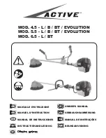
These four 25.4mL Petrol Brushcutters have been developed as
the successor models of
EBH252U/EBH252L
and
EBH253U/EBH253L
equipped with 24.5mL 4-stroke engine.
Their main feature is the multi-position engine lubrication system.
This unique system enables the engine to be inclined to any angle
even during continuous operation with no emission of white smoke
and smell of burning engine oil for wider application range of the
brushcutters.
EM2651UH and EM2651LH
additionally feature rapid start.
EM2650UH and EM2651UH are Bike handle models.
EM2650LH and EM2651LH are Loop handle models.
Net weight
*4
: kg (lbs)
5.1 (11.2)
*1
Brazil: 25E gasoline
*2
No load speed of the cutting tool
*3
Of asymmetrical design
*4
Dry weight, without universal guard, cutting tool and shoulder harness
Note:
The standard equipment for the tool shown above may vary by country.
Cutting tool ......................................................................................... 1
Universal guard (=Protector)
............................................................. 1
Shoulder harness with double shoulder straps
................................... 1 (for
EM2650UH, EM2651UH
)
Shoulder harness with single shoulder strap
...................................... 1 (for
EM2650LH, EM2651LH
)
Socket wrench
.................................................................................... 1
Hex wrench (for M4)
......................................................................... 1
Hex wrench (for M5)
......................................................................... 1
Wire clamp (for tying cables) ............................................................. 2 (for
EM2650UH
)
Oil bottle without oil or Oil bottle containing 80mL engine oil ......... 1
Accessory bag
.................................................................................... 1
Metal blades [230mm (9") 3-tooth, 4-tooth, 8-tooth], Nylon cutting heads [Ultra auto 4, Bump & feed 4,
Bump & feed Z5], Gardening attachments (for
EM2650LH, EM2651LH
)
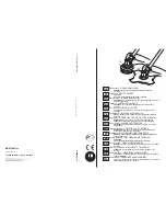
620 (24-3/8)
330 (13)
Dimensions: mm (")
Width (W)
Height (H)
Length (L)
1,765 (69-1/2)
474 (18-5/8) 264 (10-3/8)
EM2650UH
EM2651UH
EM2650LH
EM2651LH
Rapid start
EM2650UH
EM2651LH
EM2651UH
Bike handle
*3
Loop handle
Bike handle
*3
5.5 (12.1)
5.2 (11.4)
5.6 (12.3)
6,630
7370
6,630
7370
Straight unleaded gasoline
*1
0.6 (20.3)
25.4 (1.5)
Max. output: kW
Max. torque: N.m
1.1 [at 5,500 min-
1
]
0.77 [at 7,000 min-
1
]
4-stroke
Recoil starter, with mechanical decompression
SAE10W-30 oil
in the Class SF or higher of API Classification
Diaphragm
Spindle thread size
Primer pump
Yes
Clutch
Yes
M10, Left-handed
Yes
Yes
No
No
No
No
No
Yes
No load speed
*2
: min.
-1 =
rpm
Waist cushion
Model No.
T
ECHNICAL INFORMATION
EM2650UH
EM2651UH
EM2650LH
EM2651LH
L
L
H
H
W
W