96
DBC 130II
DBC130II ISE41
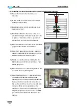
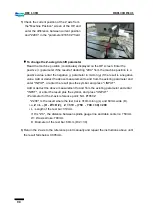
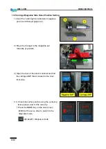
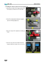
16.2 Resetting the reference point for the X axis (X-axis stroke: 3000mm)
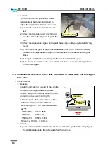
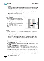
1) Return the X axis to the reference point
manually.
2) In MDI mode, move the X axis to the middle
stroke position (X1500).
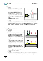
3) Install the test bar into the spindle and move
the W axis to "W0.".
4) Install the indicator in the center of the table
about 400mm high. In Handle mode, move the
Z axis in "-" direction so that it is positioned
about 30mm from the end of the test bar.
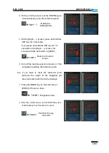
5) Move the indicator on the table deck so that the
gauge needle contacts on the test bar.
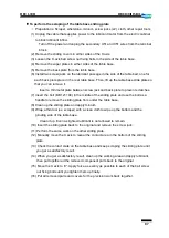
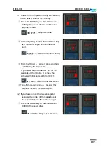
6) Move the Y axis and stop moving it when the
needle is positioned at the highest point of the
test bar. (Do NEVER move the X axis.)
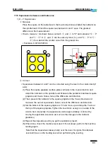
7) Rotate the spindle and stop rotating it at the
intermediate point of the test bar runout. Then,
set the gauge to 0.
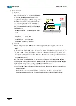
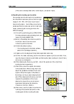
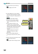
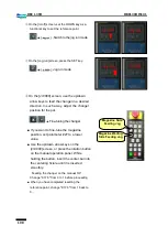
8) Move the Z axis in "+" direction by 400mm, and
rotate the B axis by 180 degrees.
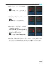
9) Move the Z axis back in "-" direction and stop
right before the test bar contacts on the
indicator. Check if there occurs an interference
between indicator needle and end section of
the test bar. And if so, move the X axis to work
it around. (If the error is ignorable by the
indicator or there occurs no interference, just
skip this step) Then, move the Z axis until it is
positioned about 30mm from the end of the
test bar.
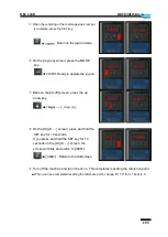
180
˚
회전
Summary of Contents for DBC 130 II
Page 1: ...Installation Manual DBC 130Ⅱ Machine Tools ...
Page 2: ......
Page 7: ...5 DBC 130II DBC130II ISE41 Ref 2 Right View Ref 3 Top View ...
Page 9: ...7 DBC 130II DBC130II ISE41 Ref 6 Top view of machine to install semi splash guard on Optional ...
Page 10: ...8 DBC 130II DBC130II ISE41 Ref 7 Top view of machine to install APC on Optional ...
Page 12: ...10 DBC 130II DBC130II ISE41 60 Tool Magazine ...
Page 60: ...58 DBC 130II DBC130II ISE41 Z axis ...
Page 121: ...119 DBC 130II DBC130II ISE41 19 Installation Complete ...

