90
DBC 130II
DBC130II ISE41
②
Correct
As the angle division of the index table is performed using the precise position coder
and mechanical devices, it is unlikely to make an error. However, if you encounter a
significant error, that's because the position coder or mechanical device inside the
table is contaminated with dust and impurities, or it is defective, damaged, or worn
out. If this is the case, you have no other option but to replace the position coder or
the mechanical device with a new one.
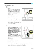
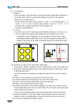
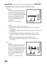
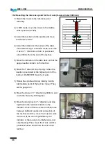
15.8 Parallelism of the X-axis movement for the T-slot
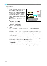
1) How to measure
Set the reference point for the B axis and
perform the table locating as well as the table
clamping. Then, install the indicator on the
spindle and present the gauge to the second T-
hole of the table T-holes. While rotating the X
axis, measure the parallelism.
▪
Measuring point : Full stroke of the table T-
hole
▪
Tolerance: 0.04mm / full stroke
`
2) Correct
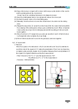
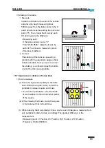
Reset the B-axis reference point and reset the locating bush position as appropriate.
▪
Resetting the reference point for the B axis
☞
The overall gear ratio of the B axis is 1440:1. That means that the B axis rotates
once when the servo motor revolves 1440 times, so the maximum degree of the B
axis per one revolution of the servo motor is 0.25
˚. Thus, the grid shaft should be
adjusted within ±125.
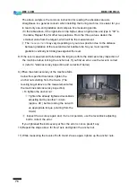
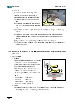
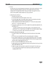
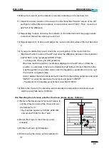
(1) Set the reference point for the B axis.
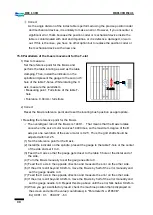
(2) Install the indicator on the spindle, present the gauge to the table T-hole or the center
of the side and set it to 0.
(3) Feed the X axis so that the gauge gets closer to the table T-hole or the distal end of
the side.
(4) Turn the B axis manually to set the gauge needle to 0.
(5) Feed the X axis in the opposite direction and measure the error on the other side.
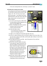
(6) If the error is still beyond 0.02mm, move the B axis by half of the error manually and
set the gauge needle to 0.
(7) Feed the X axis in the opposite direction and measure the error on the other side.
(8) If the error is still beyond 0.02mm, move the B axis by half of the error manually and
set the gauge needle to 0. Repeat this step above until the error falls below 0.02mm.
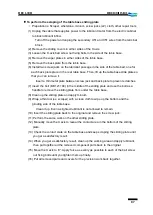
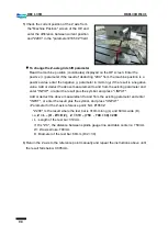
(9) When you get a satisfactory result, check the machine position that is displayed on
the screen and enter the value (coordinates) in "Parameter No. #1850 B".
Ex) 0.091 : 91, 359.937 : -63
X axis
Summary of Contents for DBC 130 II
Page 1: ...Installation Manual DBC 130Ⅱ Machine Tools ...
Page 2: ......
Page 7: ...5 DBC 130II DBC130II ISE41 Ref 2 Right View Ref 3 Top View ...
Page 9: ...7 DBC 130II DBC130II ISE41 Ref 6 Top view of machine to install semi splash guard on Optional ...
Page 10: ...8 DBC 130II DBC130II ISE41 Ref 7 Top view of machine to install APC on Optional ...
Page 12: ...10 DBC 130II DBC130II ISE41 60 Tool Magazine ...
Page 60: ...58 DBC 130II DBC130II ISE41 Z axis ...
Page 121: ...119 DBC 130II DBC130II ISE41 19 Installation Complete ...

