99
DBC 130II
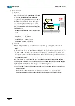
DBC130II ISE41
16.4 Resetting the reference point for the Y axis (Y-axis stroke: 2000mm)
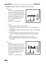
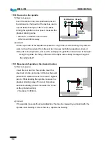
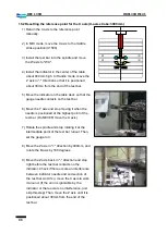
1) Insert the test bar into the spindle.
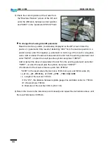
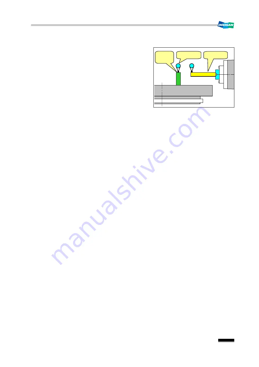
2) Put the block gauge (over 150mm) on the
pallet deck, and install the indicator on it. Then,
set the height of the block gauge to “0”.
3) Move the Y axis according to the calculation of
the below formula.
Y axis coordinates = L (height of block gauge) – D/2 (radius of test bar)
Ex) If the height of the block gauge is 150mm,
150 - 30 = 120
or, Y120.
If the test bar is not available so you work directly on the boring spindle,
150 – 65 = 85 or, Y85.
▪
If DB130CX is "Y.0", the spindle is positioned at the center of the table deck.
However, if APC is optionally installed, the distance between table deck and center
of the spindle is 250mm.(Formula: Y = L – (D/2 + 250)
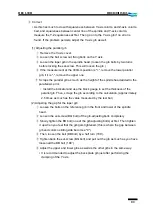
4) Install the indicator on the top of the test bar and rotate the spindle while reading the
runout on the test bar. Stop rotating the spindle at an intermediate value of the runout.
5) Move the Y axis to set the indicator needle to "0".
6) Check the measuring value of the machine position (coordinates) displayed on the main
OP screen and compare it with the result of step 3) above. Enter the positive (+)
parameter if it’s greater than the result of step 3, or the negative (-) parameter if less.
Add the above measurement to the existing parameter and press "INPUT", or add the
positive symbol (+) to the above measurement and enter "+INPUT".
▪
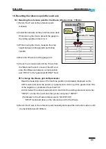
Parameter for the Y-axis reference point: NO. #1850 Y
7) Adjust the reference point of the machine and repeat steps 1) ~ 6) above again until the
measurement is within 0.05 mm.
Block
Gauge
Table
Test Bar
Indicator
Summary of Contents for DBC 130 II
Page 1: ...Installation Manual DBC 130Ⅱ Machine Tools ...
Page 2: ......
Page 7: ...5 DBC 130II DBC130II ISE41 Ref 2 Right View Ref 3 Top View ...
Page 9: ...7 DBC 130II DBC130II ISE41 Ref 6 Top view of machine to install semi splash guard on Optional ...
Page 10: ...8 DBC 130II DBC130II ISE41 Ref 7 Top view of machine to install APC on Optional ...
Page 12: ...10 DBC 130II DBC130II ISE41 60 Tool Magazine ...
Page 60: ...58 DBC 130II DBC130II ISE41 Z axis ...
Page 121: ...119 DBC 130II DBC130II ISE41 19 Installation Complete ...

