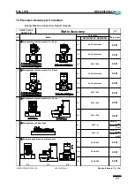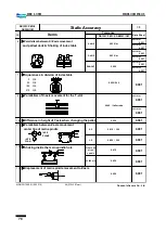
75
DBC 130II
DBC130II ISE41
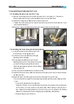
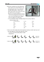
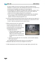
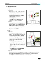
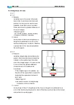
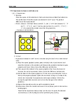
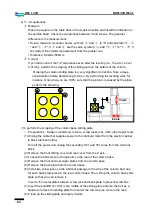
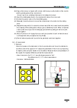
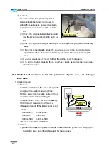
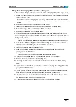
6) Place the completed level in the grinding side
of the column in the X and Z directions. Then,
while feeding the Z axis to the coordinates of
"Z0. Z400. Z800. Z1200. Z1600." in five
distinct steps, perform the leveling in the same
way with the X-axis leveling above.
▪
However, you must be careful for the change
to the X axis leveling while working on the Z
axis. (It is recommended to place another
level on the table for your reference.)
▪
It is recommended to make coordinate settings for the leveling in advance.
※
Setting example) O 002;
G90 G00 G54 Z0.; Z1200.; Z800;
M01; M01 M01
Z400.; Z1600; Z400.;
M01; M01; M01
Z800.; Z1200; M99;
M01; M01;
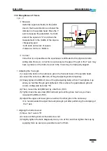
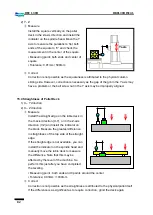
7) Take a note of the leveling values while repeating the leveling on both X and Z axes until
the overall difference of the leveling falls below 0.02/m.
①
To take a note of the leveling values on paper
▪
Sample Note
X axis
Z axis
10
15
20
20
30
30
X axis: 20
Z axis: 15
▪
Z Axis:
▪
X Axis: Z axis
10
20
30
Z axis: 20
X axis: 10
15
20
25
X axis
10
15
10
15
30
30
Summary of Contents for DBC 130 II
Page 1: ...Installation Manual DBC 130Ⅱ Machine Tools ...
Page 2: ......
Page 7: ...5 DBC 130II DBC130II ISE41 Ref 2 Right View Ref 3 Top View ...
Page 9: ...7 DBC 130II DBC130II ISE41 Ref 6 Top view of machine to install semi splash guard on Optional ...
Page 10: ...8 DBC 130II DBC130II ISE41 Ref 7 Top view of machine to install APC on Optional ...
Page 12: ...10 DBC 130II DBC130II ISE41 60 Tool Magazine ...
Page 60: ...58 DBC 130II DBC130II ISE41 Z axis ...
Page 121: ...119 DBC 130II DBC130II ISE41 19 Installation Complete ...

