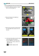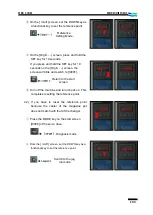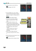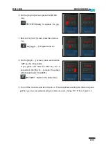
92
DBC 130II
DBC130II ISE41
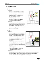
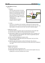
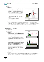
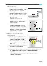
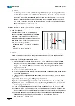
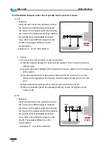
15.9 Parallelism between center line of spindle and movement of Z-axis
1) X-Z
①
Measure
Insert the test bar into the spindle and move
the X axis up to 300mm away to measure
the runout on the highest point (stop moving
the Y axis at the highest point). Stop rotating
the spindle at an intermediate point and
move the Z axis to 300mm away from the
mouth. The greatest difference is the
measurement.
▪
Tolerance: X
-
Z: 0.015mm/300mm
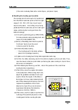
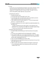
②
Correct
▪
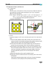
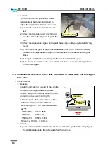
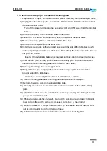
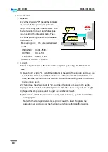
This is to restore the accuracy of the column itself.
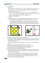
(1) Set the indicator needle to 0 at the test bar position. Then, move the Z axis to
300mm away.
(2) Loosen the bolts (10-BA24×100) except for the reamer bolts in the front right side
of the column.
(3) Use the adjusting bolt on the position block (under the column) to move the
column in the opposite to the indicator direction about 5 times as much as the
error.
(4) Repeat these instructions above until you get a satisfactory result.
(5) When completed, tighten the adjusting bolts (x2) evenly and tighten up the
column bolts.
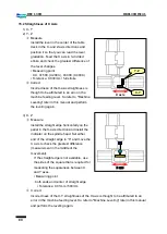
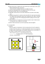
2) Y-Z
①
Measure
Insert the test bar into the spindle and move
the Y axis up to 300mm away to measure
the runout on the highest point (stop moving
the X axis at the highest point). Stop rotating
the spindle at an intermediate point and
move the Z axis to 300mm away from the
mouth. The greatest difference is the
measurement.
▪
Tolerance: Y
-
Z: 0.015mm/300mm
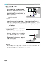
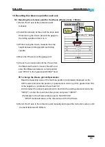
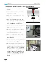
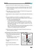
Z axis
Y-Z
Z axis
X-Z
Summary of Contents for DBC 130 II
Page 1: ...Installation Manual DBC 130Ⅱ Machine Tools ...
Page 2: ......
Page 7: ...5 DBC 130II DBC130II ISE41 Ref 2 Right View Ref 3 Top View ...
Page 9: ...7 DBC 130II DBC130II ISE41 Ref 6 Top view of machine to install semi splash guard on Optional ...
Page 10: ...8 DBC 130II DBC130II ISE41 Ref 7 Top view of machine to install APC on Optional ...
Page 12: ...10 DBC 130II DBC130II ISE41 60 Tool Magazine ...
Page 60: ...58 DBC 130II DBC130II ISE41 Z axis ...
Page 121: ...119 DBC 130II DBC130II ISE41 19 Installation Complete ...

