72
DBC 130II
DBC130II ISE41
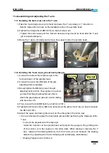
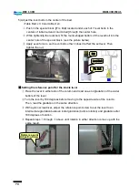
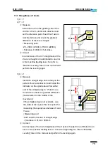
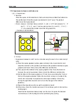
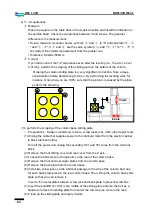
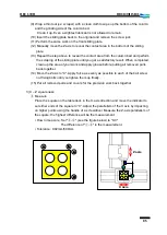
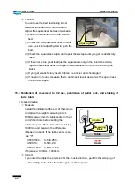
1) Move the machine to the coordinates of X1500. Y1000. Z800.
2) Clean up the table deck and place the level in the center of the table. Then, perform the
"setting the reference point for the level"
※
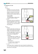
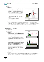
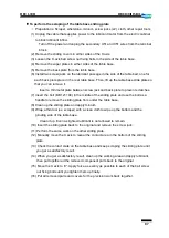
Setting the reference point for the X-axis level
①
Place the level in the center of the table and read one-end gradation of the water
bubble of the level.
②
Turn the level by 180 degrees and read the gradation in the same direction.
③
With a plain screwdriver, adjust the reference point screw to set the level to an
intermediate gradation between initial gradation (before rotation) and gradation after
180 degrees of rotation.
④
Repeat steps
①
through
③
above until rotation in either direction comes up with the
same result.
※
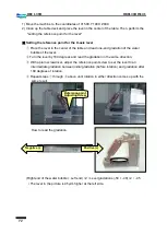
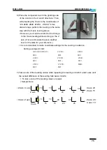
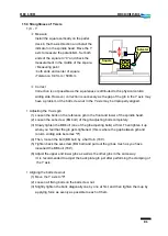
How to read the gradation
(Right end of the water Left end) ÷2
=
Level gradations (-50 + -40) ÷2
=
- 45
▪
The level in the picture is 45μ/m higher at the left side.
Reference-point
Adjusting Screw
Negative (-)
Positive (+)
Summary of Contents for DBC 130 II
Page 1: ...Installation Manual DBC 130Ⅱ Machine Tools ...
Page 2: ......
Page 7: ...5 DBC 130II DBC130II ISE41 Ref 2 Right View Ref 3 Top View ...
Page 9: ...7 DBC 130II DBC130II ISE41 Ref 6 Top view of machine to install semi splash guard on Optional ...
Page 10: ...8 DBC 130II DBC130II ISE41 Ref 7 Top view of machine to install APC on Optional ...
Page 12: ...10 DBC 130II DBC130II ISE41 60 Tool Magazine ...
Page 60: ...58 DBC 130II DBC130II ISE41 Z axis ...
Page 121: ...119 DBC 130II DBC130II ISE41 19 Installation Complete ...

