14
DBC 130II
DBC130II ISE41
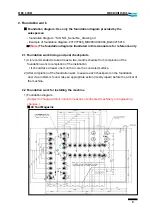
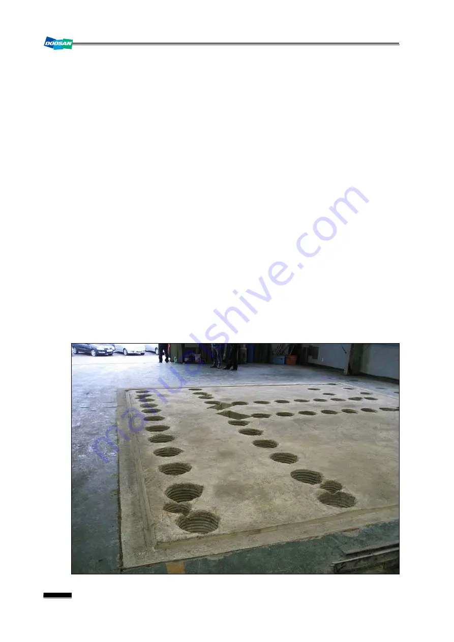
Note) 1) Reinforce the ground with stake driving, riprap piling and rebar reinforcement.
(bearing power of soil: at least 10 tons/m²)
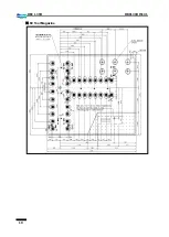
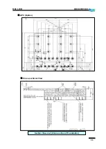
2) Tolerance for each foundation checkpoint
▪
Top view: ±10mm
▪
Gap between holes: ±10mm
▪
Cumulative gaps between holes : ±20mm
▪
Size of foundation hole: ±10mm
3) It should take at least one month to cure the primary concreted surface.
4) Prepare the wiring between electric cabinet and main power as well as air service
unit as appropriate for the work.
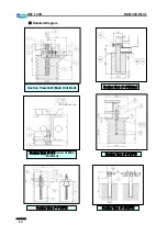
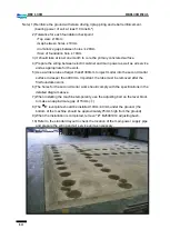
5) Use a wrinkle tube of larger than Ø300mm to inject mortar into the second mortar
surface in deeper than 400mm. Important: the tube must be removed after the
first foundation work.
6) The holes for the second mortar work should comply with the specifications in the
detailed diagram above.
7) When installing the machine temporarily, use the adjusting bolt on the level block
to make an approximate gap of 15mm.(
ⓐ
)
8) The
“
6”
level plate should be installed 10mm~40mm under the ground. (the
bottom of the machine should be approximately 75mm high from the ground)
9) When the installation is completed, remove
“2”
B26491014 adjusting bush.
10) Refer to the standard layout to check the location of the main power supply pipe
and prepare the wiring and air service unit as necessary.
Summary of Contents for DBC 130 II
Page 1: ...Installation Manual DBC 130Ⅱ Machine Tools ...
Page 2: ......
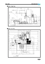
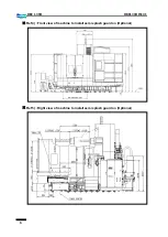
Page 7: ...5 DBC 130II DBC130II ISE41 Ref 2 Right View Ref 3 Top View ...
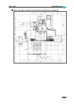
Page 9: ...7 DBC 130II DBC130II ISE41 Ref 6 Top view of machine to install semi splash guard on Optional ...
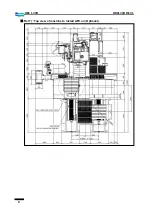
Page 10: ...8 DBC 130II DBC130II ISE41 Ref 7 Top view of machine to install APC on Optional ...
Page 12: ...10 DBC 130II DBC130II ISE41 60 Tool Magazine ...
Page 60: ...58 DBC 130II DBC130II ISE41 Z axis ...
Page 121: ...119 DBC 130II DBC130II ISE41 19 Installation Complete ...


