91
DBC 130II
DBC130II ISE41
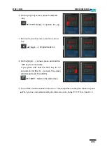
(If the item is already filled with a certain figure, just press +Input).
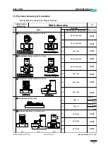
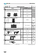
▪
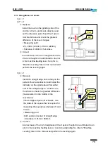
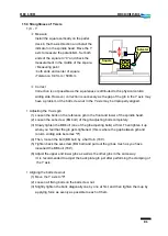
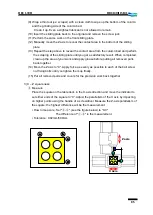
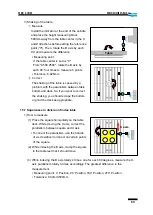
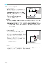
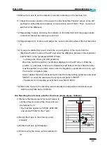
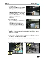
Resetting the locating push position
The locating pin or bush may be mis-positioned
from the B-axis reference point or from the right
angle (0
˚, 90˚, 180˚, 270˚) due to such as an
impact on the table. Even if they are correctly
positioned from the reference point or each right
angle, performing the locating will move the
table accordingly.
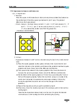
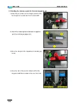
(1) Pull out the positioning pins (2-SPB 10X50)
from the problem-making locating bush and
loosen the bolts (6-BB12×30).
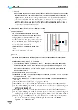
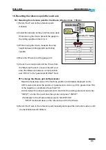
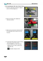
(2) Refer to "Resetting the reference point for
the B axis" above to set the exact
reference point for the table.
(3) Perform the table locating.
⇒
The locating bush in the table will take
place in the locating pin position.
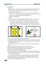
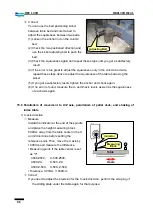
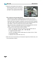
(4) Tighten up the locating bush fixing bolts (applicable bolts only)
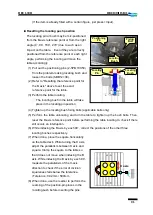
(5) Perform the table unlocating and turn the table to tighten up the bush bolts. Then,
reset the B-axis reference point before performing the table locating to check if there
still occurs an interruption.
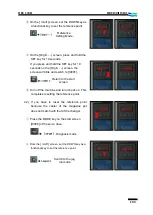
(6) While indexing the B axis by each 90
˚, correct t
he positions of the other three
locating bushes respectively.
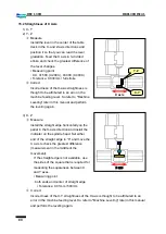
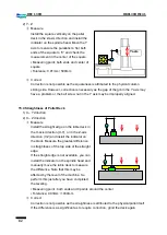
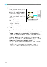
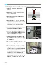
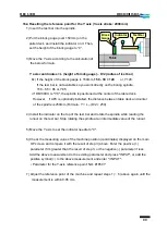
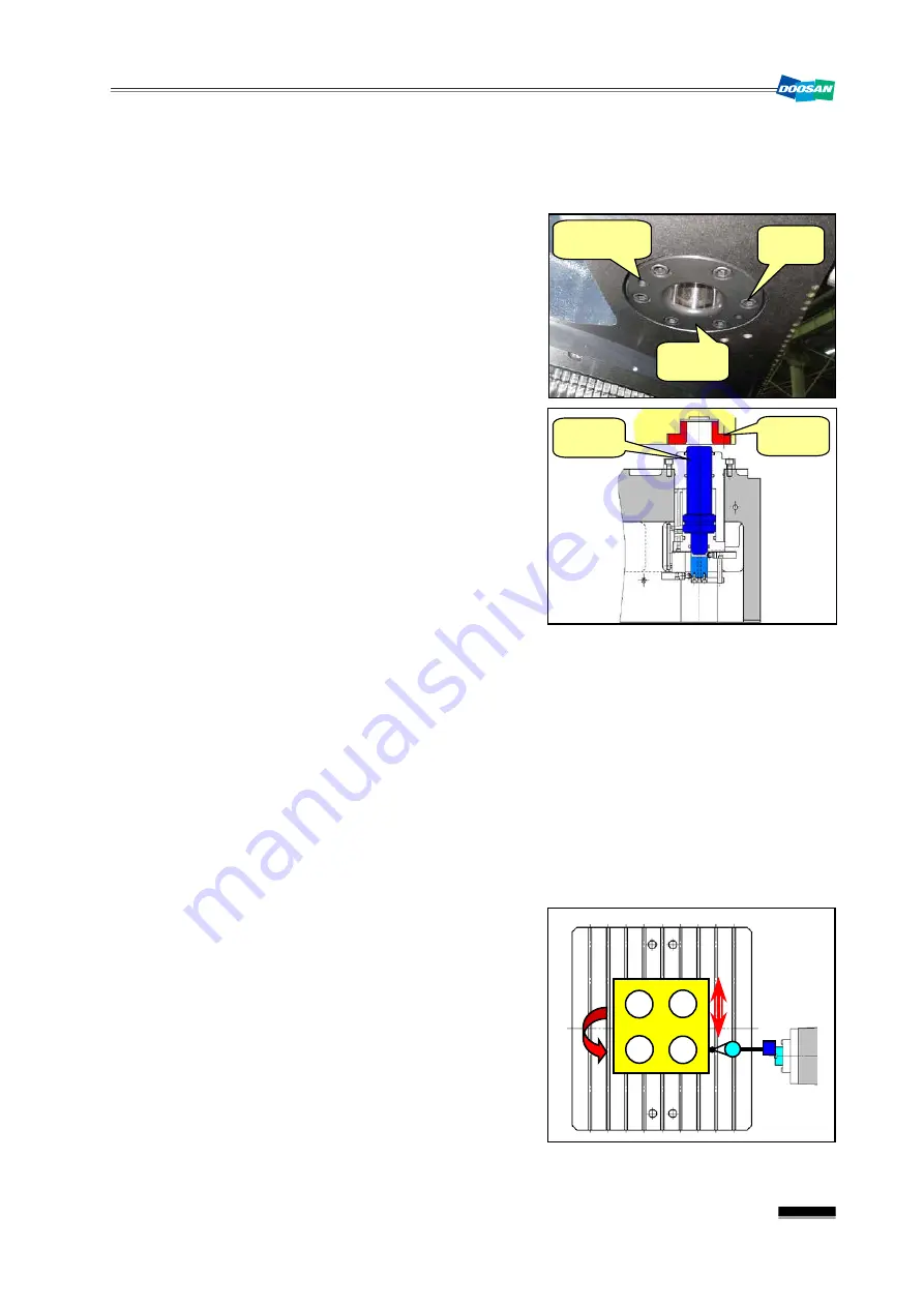
(7) When done, place the square horizontally
on the table deck. While turning the X axis,
adjust the parallelism between X axis and
square. Clamp the square to the table so
that it does not move when indexing the B
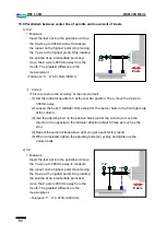
axis. While indexing the B axis by each 90
˚,
measure the parallelism of the X-axis
direction to check if the error of division
squareness falls below the tolerance.
▪
Tolerance: 0.02mm / 500mm
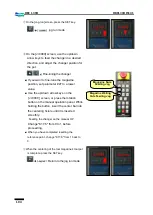
(8) When done, use the reamer to perform the
reaming of the position-pin places in the
locating bush before inserting the pins.
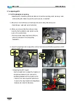
X axis
Locating
Bush
Fixing
Bolt
Positioning
Pin
Locating
Bush
Locating
Pin
Summary of Contents for DBC 130 II
Page 1: ...Installation Manual DBC 130Ⅱ Machine Tools ...
Page 2: ......
Page 7: ...5 DBC 130II DBC130II ISE41 Ref 2 Right View Ref 3 Top View ...
Page 9: ...7 DBC 130II DBC130II ISE41 Ref 6 Top view of machine to install semi splash guard on Optional ...
Page 10: ...8 DBC 130II DBC130II ISE41 Ref 7 Top view of machine to install APC on Optional ...
Page 12: ...10 DBC 130II DBC130II ISE41 60 Tool Magazine ...
Page 60: ...58 DBC 130II DBC130II ISE41 Z axis ...
Page 121: ...119 DBC 130II DBC130II ISE41 19 Installation Complete ...


