84
DBC 130II
DBC130II ISE41
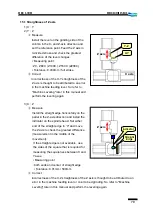
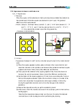
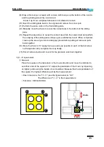
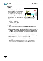
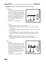
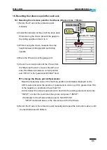
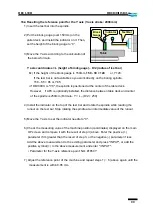
2) Y – Z squareness
ⓐ
Measure
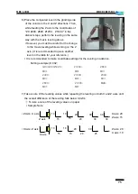
Place the square on the table deck in the Z-axis direction and install the indicator on
the spindle head. Check the squareness between Y and Z axes. The greatest
difference is the measurement.
▪
How to measure: As shown below, set both
ⓑ
and
ⓒ
to "0" and calculate "
ⓑ-ⓐ
" and "
ⓒ-ⓓ
". If
ⓐ
and
ⓓ
are the same symbol (+/-), add "
ⓑ-ⓐ
" to "
ⓒ-ⓓ
", if
not, deduct the smaller measurement from the greater one.
▪
Tolerance: 0.02mm/500mm
ⓑ
Correct
If you fail to correct the Y-Z squareness even after the leveling (i.e., the error is over
0.01mm), perform the scraping of the sliding plate on the bottom of the column.
※
Scraping the column sliding plate is a very significant correction. Take a deep
consideration before determining to do so. Try performing the leveling work, for
instance. Only when you are 100% sure that the problem is caused by the plate,
perform the scraping.
▪
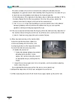
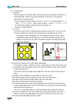
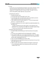
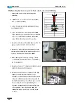
To perform the scraping of the column base sliding plate
☞
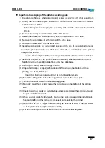
Preparations : Scraper, whetstone, minium, screw jacks (x2), cloth, other repair tools
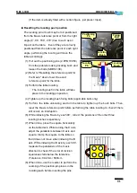
(1) Unplug the cable that supplies power to the lubricant motor from the electric cabinet
to block lubricant inflow.
※
Turn off the power and unplug the secondary U51 and V51 wires from the terminal
block.
(2) Remove the front sliding cover and rear cover from the Z axis.
(3) Loosen the ball screw nut fixing bolts on the rear of the column base.
(4) Remove the front and rear wiper plates from the column base.
(5) Remove the back plate from the column base.
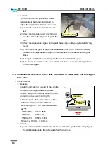
(6) Install two screw jacks on the lubricant passage in the side of the column bed, one
for each back plate place in the rear column base. Then, lift up the column base slide
plate so that you can remove it.
※
Insert a thin metal plate between screw jack and back plate to prevent scratches.
(7) Insert the bolt (BB 12×100) in the middle of the sliding plate and use the bolt as a
handle to remove the sliding plate from under the column.(one more in the rear)
(8) Clean up the sliding plate and apply minium.
Y axis
Z axis
b
a
c
d
Summary of Contents for DBC 130 II
Page 1: ...Installation Manual DBC 130Ⅱ Machine Tools ...
Page 2: ......
Page 7: ...5 DBC 130II DBC130II ISE41 Ref 2 Right View Ref 3 Top View ...
Page 9: ...7 DBC 130II DBC130II ISE41 Ref 6 Top view of machine to install semi splash guard on Optional ...
Page 10: ...8 DBC 130II DBC130II ISE41 Ref 7 Top view of machine to install APC on Optional ...
Page 12: ...10 DBC 130II DBC130II ISE41 60 Tool Magazine ...
Page 60: ...58 DBC 130II DBC130II ISE41 Z axis ...
Page 121: ...119 DBC 130II DBC130II ISE41 19 Installation Complete ...

