110
DBC 130II
DBC130II ISE41
17.4 Fine-tuning the spindle side of the changer arm
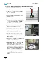
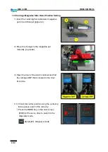
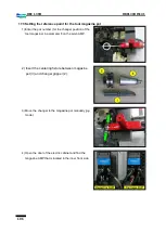
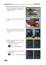
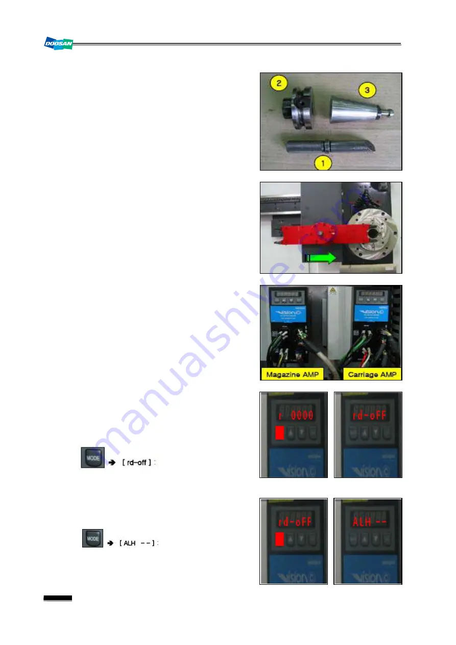
1) Remove the driving key from the spindle and
insert the centering fixture (3) and changer
gripper (2) as well.
2) In jog mode, move the changer to the spindle side
position.
3) Open the door of the electric cabinet and find
the carriage AMP that is located in the internal
front side.
4) On the front operation panel, make necessary
settings for the work.
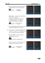
①
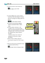
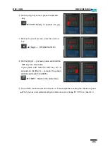
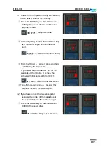
Press the MODE key on the start screen
[r0000] of the servo drive.
②
On the [rd-off] screen, press the MODE key
to display [ALH - - ].
Diagnosis mode
Alarm history display mode
Summary of Contents for DBC 130 II
Page 1: ...Installation Manual DBC 130Ⅱ Machine Tools ...
Page 2: ......
Page 7: ...5 DBC 130II DBC130II ISE41 Ref 2 Right View Ref 3 Top View ...
Page 9: ...7 DBC 130II DBC130II ISE41 Ref 6 Top view of machine to install semi splash guard on Optional ...
Page 10: ...8 DBC 130II DBC130II ISE41 Ref 7 Top view of machine to install APC on Optional ...
Page 12: ...10 DBC 130II DBC130II ISE41 60 Tool Magazine ...
Page 60: ...58 DBC 130II DBC130II ISE41 Z axis ...
Page 121: ...119 DBC 130II DBC130II ISE41 19 Installation Complete ...

