


Chapter 6 Control Modes of Operation
ASDA-A User Manual
4th Edition 2005/11/30, HE03
© DELTA ELECTRONICS, INC. ALL RIGHTS RESERVED
6-14
6-3-1 Command Source of Speed Control Mode
Speed command Source:
1. External analog signal: External analog voltage input, -10V to +10V
2. Internal parameter: P1-09 to P1-11
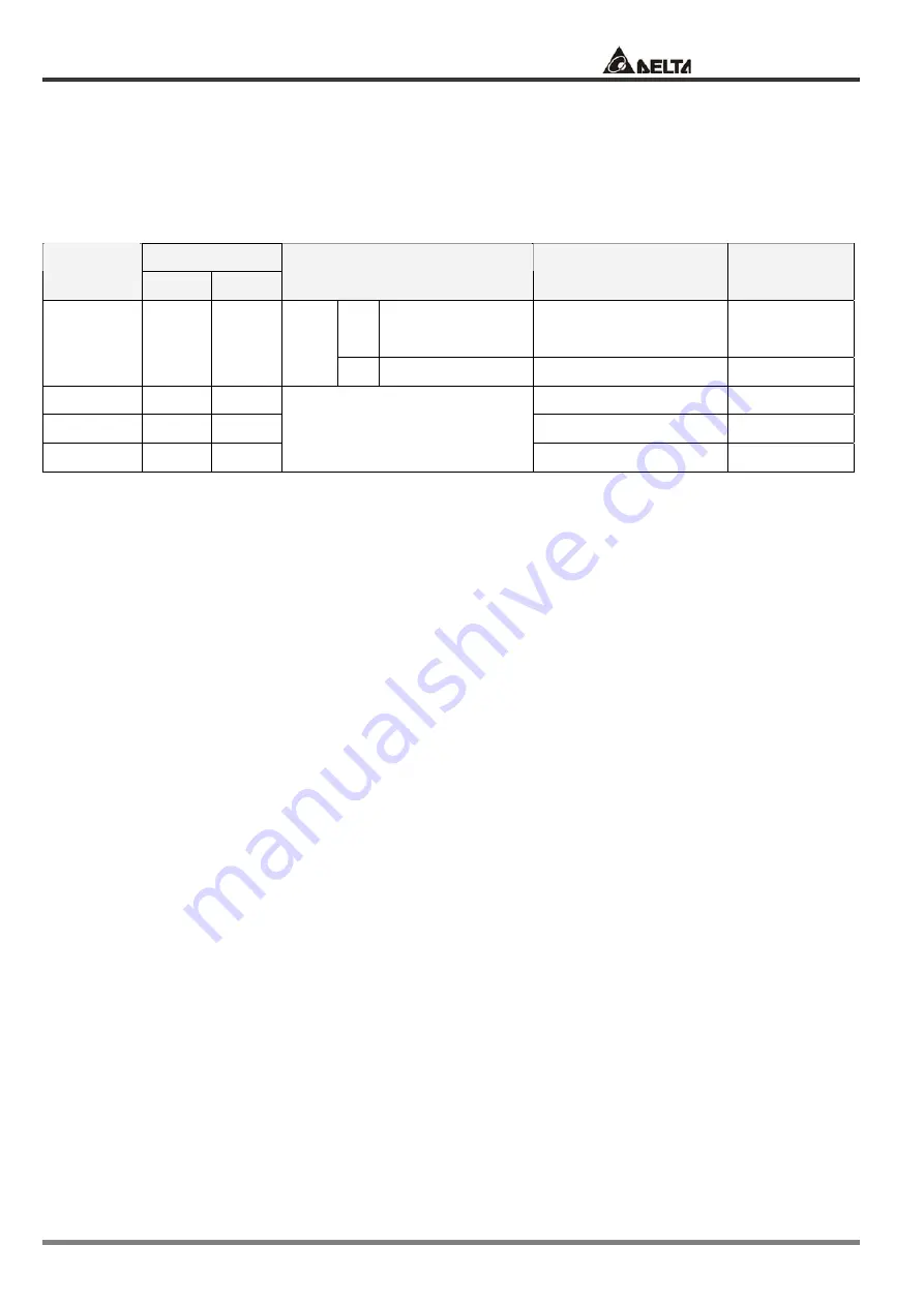
DI signal of CN1
Speed
Command
SPD1
SPD0
Command Source
Content
Range
S
External analog
signal
Voltage between
V-REF-GND
+/-10 V
S1 0
0
Mode
Sz None
Speed command is 0
0
S2 0
1
P1-09 0~5000
rpm
S3 1
0
P1-10
0~5000 rpm
S4 1
1
Internal parameter
P1-11
0~5000 rpm
State of SPD0~1
:
0: indicates OFF (Normally Open)
1: indicates ON (Normally Closed)
When
SPD0=SPD1=0 (OFF)
, if the control mode of operation is Sz, then the command is 0. Therefore,
if users do not use analog voltage as speed command, users can choose Sz mode to operation speed
control to avoid the zero point drift problem of analog voltage. If the control mode of operation is S, then
the command is the analog voltage between
V-REF and GND.
The setting range of the input voltage is
from -10V to +10V and the corresponding rotation speed is adjustable (see parameter P1-40).
When one of
SPD0 and SPD1 is not 0 (OFF)
, the speed command is internal parameter. The
command is valid (enabled) after
SPD0~1 is changed and it doesn’t need that CTRG should be
triggered.
The speed command that is described in this section not only can be taken as speed command in speed
control mode (S or Sz mode) but also can be the speed limit input command in torque control mode (T or Tz
mode).


