background image

82

Installing System Components

Installing the Front Bezel

1

Insert the bezel tabs into the bezel tab slots in the chassis. See Figure 3-2.

2

Press the top end of the bezel into the chassis until the lever locks 
into place. 

3

Using the system key, lock the bezel.

Front Bezel Inserts

Removing the Front Bezel Insert


NOTE: 

Before installing a drive in one or more of the front drive bays, remove the 

corresponding insert(s) on the front bezel.


NOTE: 

Bezel inserts may contain screws on the inside. You can attach the screws 

to new drives, as needed.

1

Remove the front bezel. See "Removing the Front Bezel" on page 81.

2

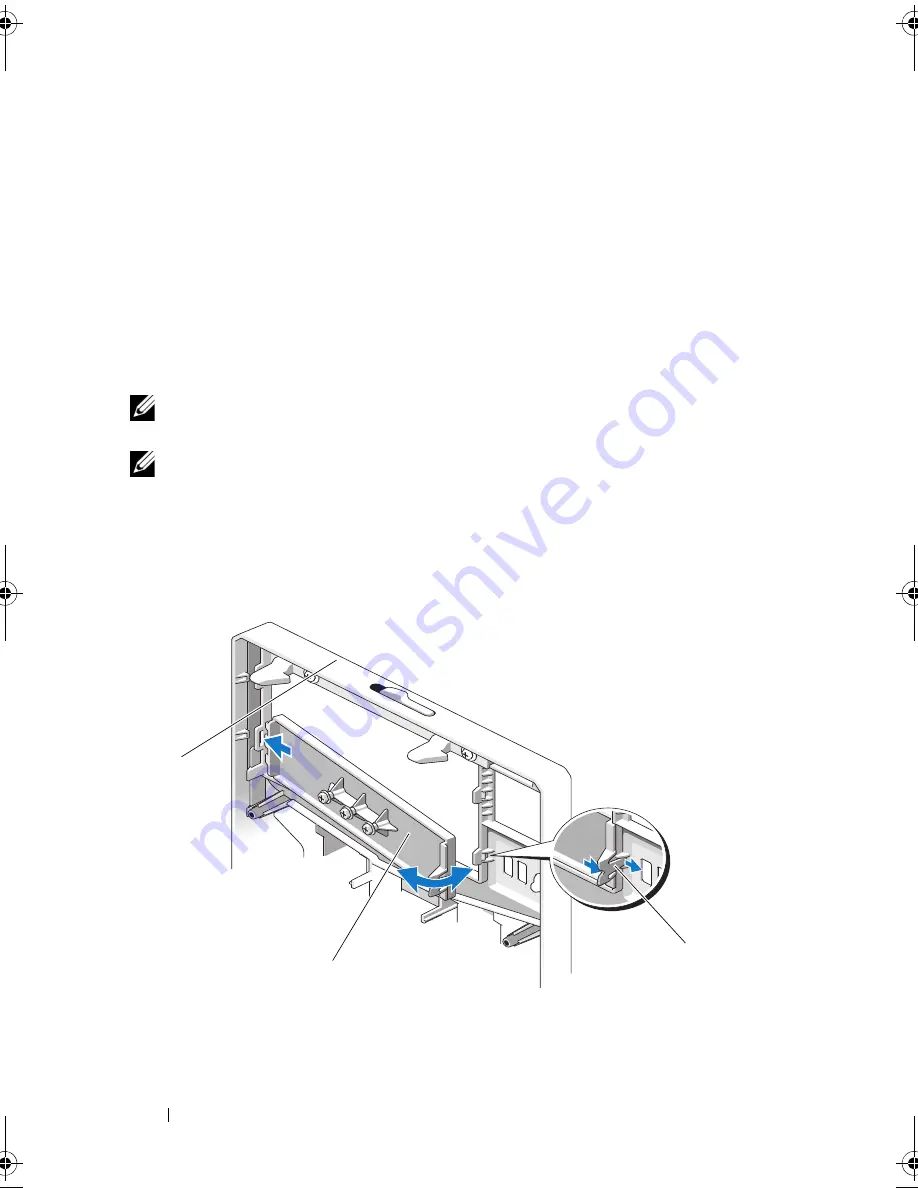
Press the insert tab and pull the insert away from the bezel. See Figure 3-3.

Figure 3-3.

Removing and Installing the Front Bezel Insert

1

front bezel

2

front bezel insert

3

insert tab

1

3

2

book.book  Page 82  Wednesday, August 19, 2009  4:40 PM

Summary of Contents for PowerEdge T310

Page 1: ...Dell PowerEdge T310 Systems Hardware Owners Manual ...

Page 2: ...rved Reproduction of these materials in any manner whatsoever without the written permission of Dell Inc is strictly forbidden Trademarks used in this text Dell the DELL logo and PowerEdge are trademarks of Dell Inc MS DOS Microsoft Windows and Windows Server are either trademarks or registered trademarks of Microsoft Corporation in the United States and or other countries Other trademarks and tra...

Page 3: ... 15 Setup Menu 16 View Menu 17 Hard Drive Indicator Patterns 18 Back Panel Features and Indicators 19 Guidelines for Connecting External Devices 21 NIC Indicator Codes 21 Power Indicator Codes 22 Diagnostic Lights Optional 23 LCD Status Messages 25 Viewing Status Messages 26 Removing LCD Status Messages 26 System Messages 39 Warning Messages 54 Diagnostics Messages 54 ...

Page 4: ...ons 59 Main Screen 59 Memory Settings Screen 61 Processor Settings Screen 62 SATA Settings Screen 62 Boot Settings Screen 63 Integrated Devices Screen 64 PCI IRQ Assignment Screen 65 Serial Communication Screen 65 Embedded Server Management Screen Optional 66 Power Management Screen 66 System Security Screen 67 Exit Screen 69 Entering the UEFI Boot Manager 69 Using the UEFI Boot Manager Navigation...

Page 5: ...lity 77 3 Installing System Components 79 Recommended Tools 79 Inside the System 79 Front Bezel 81 Removing the Front Bezel 81 Installing the Front Bezel 82 Front Bezel Inserts 82 Removing the Front Bezel Insert 82 Installing the Front Bezel Insert 83 EMI Filler Panel 83 Removing an EMI Filler Panel 83 Installing an EMI Filler Panel 84 Opening and Closing the System 85 Opening the System 85 Closin...

Page 6: ...ling a Hot Swap Hard Drive Into a Drive Carrier 95 Removing a Cabled Hard Drive 95 Installing a Cabled Hard Drive 97 Removing a Cabled Hard Drive From a Hard Drive Bracket 98 Optical and Tape Drives 99 Removing an Optical or a Tape Drive 99 Installing an Optical or Tape Drive 100 Power Supplies 103 Removing a Redundant Power Supply 103 Installing a Redundant Power Supply 104 Removing a Non Redunda...

Page 7: ...talling an iDRAC6 Express Card 119 Removing an iDRAC6 Express Card Optional 120 iDRAC6 Enterprise Card Optional 121 Installing an iDRAC6 Enterprise Card 121 Removing an iDRAC6 Enterprise Card 123 VFlash Media Optional 124 Installing a VFlash Media 124 Removing a VFlash Media 124 Internal USB Memory Keys 124 Processor 126 Removing a Processor 126 Installing a Processor 129 System Battery 130 Replac...

Page 8: ...wer Distribution Board 140 Removing the Power Distribution Board 140 Replacing the Power Distribution Board 142 System Board 142 Removing the System Board 142 Installing the System Board 144 4 Troubleshooting Your System 147 Safety First For You and Your System 147 Troubleshooting System Startup Failure 147 Troubleshooting External Connections 148 Troubleshooting the Video Subsystem 148 Troublesho...

Page 9: ...158 Troubleshooting a Tape Backup Unit 159 Troubleshooting a Hard Drive 160 Troubleshooting a SAS or SAS RAID Controller 161 Troubleshooting Expansion Cards 162 Troubleshooting the Processor 163 5 Running the System Diagnostics 165 Using Online Diagnostics 165 Embedded System Diagnostics Features 165 When to Use the Embedded System Diagnostics 166 Running the Embedded System Diagnostics 166 System...

Page 10: ...nd Results 168 6 Jumpers and Connectors 169 System Board Jumpers 169 System Board Connectors 170 SAS Backplane Board Connectors 173 Power Distribution Board Connectors 174 Disabling a Forgotten Password 174 7 Getting Help 177 Contacting Dell 177 Glossary 179 Index 189 ...

Page 11: ...Boot Manager or the UEFI Boot Manager depending on the system s boot configuration See Using the System Setup Program and UEFI Boot Manager on page 57 F12 Starts PXE boot Ctrl E Enters the Baseboard Management Controller BMC or iDRAC Configuration Utility which allows access to the System Event Log SEL and configuration of remote access to the system For more information see the BMC or iDRAC user ...

Page 12: ...1 Front Panel Features and Indicators Item Indicator Button or Connector Icon Description 1 Front bezel lock Secures the front bezel to the system 2 Tape drive Optical drive optional One optional internal half height tape backup device or an optical drive 3 Optical drive optional Optional internal SATA DVD ROM or DVD RW NOTE DVD devices are data only 5 4 7 6 8 9 2 3 10 1 ...

Page 13: ...tification button The identification button on the front panel can be used to locate a particular system When the button is pushed the LCD panel on the front flashes blue until the button is pushed again 7 Power on indicator power button The power on indicator lights when the system power is on The power button controls the DC power supply output to the system NOTE When powering on the system the ...

Page 14: ... and can be turned on by pressing the Select button on the LCD panel The LCD backlight remains off if LCD messaging is turned off through the BMC or iDRAC utility the LCD panel or other tools 8 NMI button Used to troubleshoot software and device driver errors when using certain operating systems This button can be pressed using the end of a paper clip Use this button only if directed to do so by q...

Page 15: ...rements 2 Select Selects the menu item highlighted by the cursor 3 System identification Turns the system ID mode on LCD panel flashes blue and off Press quickly to toggle the system ID on and off If the system hangs during POST press and hold the system ID button for more than five seconds to enter BIOS Progress mode 4 Right Moves the cursor forward in one step increments During message scrolling...

Page 16: ...iDRAC6 Express card is installed on the system the BMC option is replaced by DRAC Select DHCP or Static IP to configure the network mode If Static IP is selected the available fields are IP Subnet Sub and Gateway Gtw Select Setup DNS to enable DNS and to view domain addresses Two separate DNS entries are available Set error Select SEL to display LCD error messages in a format that matches the IPMI...

Page 17: ...TE If the iDRAC Express card is not installed on the system the MAC option displays the MAC addresses for BMC iSCSIn or NETn Name Displays the name of the Host Model or User String for the system Number Displays the Asset tag or the Service tag for the system Power Displays the power output of the system in BTU hr or Watts The display format can be configured in the Set home submenu of the Setup m...

Page 18: ...rn RAID Only Condition Blinks green two times per second Identify drive preparing for removal Off Drive ready for insertion or removal NOTE The drive status indicator remains off until all hard drives are initialized after system power is applied Drives are not ready for insertion or removal during this time Blinks green amber and off Drive predicted failure 1 2 ...

Page 19: ...tures and Indicators Blinks amber four times per second Drive failed Blinks green slowly Drive rebuilding Steady green Drive online Blinks green three seconds amber three seconds and off six seconds Rebuild aborted Drive Status Indicator Pattern RAID Only Condition 6 2 5 4 1 7 8 3 9 ...

Page 20: ...o the system The ports are USB 2 0 compliant 3 Ethernet connectors 2 Integrated 10 100 1000 NIC connectors 4 video connector Connects a VGA display to the system 5 serial connector Connects a serial device to the system 6 iDRAC6 Enterprise port optional Dedicated management port for the optional iDRAC6 Enterprise card 7 VFlash media slot optional Connects an external SD memory card for the optiona...

Page 21: ...e system If necessary to enable ports on your system use the System Setup program See Using the System Setup Program and UEFI Boot Manager on page 57 NIC Indicator Codes 1 link indicator 2 activity indicator Indicator Indicator Code Link and activity indicators are off The NIC is not connected to the network Link indicator is green The NIC is connected to a valid network link at 1000 Mbps Link ind...

Page 22: ...t indicates that the power supply is providing DC power to the system Amber Indicates a problem with the power supply Alternating green and amber When hot adding a power supply this indicates that the power supply is mismatched with the other power supply Replace the power supply that has the flashing indicator with a power supply that matches the capacity of the other installed power supply Figur...

Page 23: ... the system Figure 1 5 Non Redundant Power Supply Status Indicator Diagnostic Lights Optional The four diagnostic indicator lights on the system front panel display error codes during system startup Table 1 1 lists the causes and possible corrective actions associated with these codes A highlighted circle indicates the light is on a non highlighted circle indicates the light is off NOTE The diagno...

Page 24: ...formation only BIOS checksum failure detected system is in recovery mode See Getting Help on page 177 Possible processor failure See Troubleshooting the Processor on page 163 Memory failure See Troubleshooting System Memory on page 155 Possible expansion card failure See Troubleshooting Expansion Cards on page 162 Possible video failure See Getting Help on page 177 Hard drive failure Ensure that t...

Page 25: ...cted See Troubleshooting System Memory on page 155 System board failure See Getting Help on page 177 Memory configuration error See Troubleshooting System Memory on page 155 Possible system board resource and or system board hardware failure See Getting Help on page 177 Possible system resource configuration error See Getting Help on page 177 Other failure Ensure that the diskette drive optical dr...

Page 26: ...orm this task remotely but you will lose the event history for the system Power cycle Turn off the system and disconnect it from the electrical outlet wait for approximately ten seconds reconnect the power cable and restart the system NOTE The following LCD status messages are displayed in the Simple format Table 1 2 LCD Status Messages Code Text Causes Corrective Actions E1000 Failsafe voltage er...

Page 27: ...ontroller battery failure Check battery RAID battery is either missing bad or unable to recharge due to thermal issues Reseat the RAID battery connector See RAID Battery Optional on page 132 and Troubleshooting System Cooling Problems on page 154 E1216 3 3V Regulator failure Reseat PCIe cards 3 3V voltage regulator has failed Remove and reseat the PCIe expansion cards If the problem persists see T...

Page 28: ...t the memory modules See Troubleshooting System Memory on page 155 E122E On board regulator failed Call support One of the on board voltage regulators failed Remove AC power to the system for 10 seconds and restart the system If the problem persists see Getting Help on page 177 E1310 Fan RPM exceeding range Check fan RPM of fan is outside of the intended operating range See Troubleshooting System ...

Page 29: ...heck CPU or BIOS revision Processor is in an unsupported configuration Ensure that your processor matches and conforms to the type described in the processor technical specifications outlined in your system s Getting Started Guide E141F CPU protocol error Power cycle AC The system BIOS has reported a processor protocol error Remove AC power to the system for 10 seconds and restart the system If th...

Page 30: ...r supply fan failure an over temperature condition or power supply communication error has caused the predictive warning of an impending power supply failure See Troubleshooting Power Supplies on page 153 E161C Power Supply W lost AC power Check PSU cables Specified power supply is attached to the system but it has lost its AC input Check the AC power source for the specified power supply If the p...

Page 31: ...ting Started Guide E1629 Power required PSU wattage Check PSU and config The system configuration requires more power than the power supplies can provide even with throttling Turn off power to the system reduce the hardware configuration or install higher wattage power supplies and then restart the system E1710 I O channel check error Review clear SEL The system BIOS has reported an I O channel ch...

Page 32: ...bleshooting Expansion Cards on page 162 E1712 PCI system error on Bus Device Function The system BIOS has reported a PCI system error on a component that resides in PCI configuration space at bus device function Remove and reseat the PCIe expansion cards If the problem persists see Troubleshooting Expansion Cards on page 162 E1714 Unknown error Review clear SEL The system BIOS has determined there...

Page 33: ...r 10 seconds and restart the system If the problem persists see Getting Help on page 177 E1717 CPU internal error Review clear SEL The system BIOS has determined that the processor has had an internal error Check the SEL for more information and then clear the SEL Remove AC power to the system for 10 seconds and restart the system If the problem persists see Getting Help on page 177 E171F PCIe fat...

Page 34: ...rol panel is missing or bad Reseat the cable If the problem persists replace cable If the problem persists see Getting Help on page 177 E2010 Memory not detected Inspect DIMMs No memory was detected in the system Install memory or reseat the memory modules See Installing Memory Modules on page 111 or Troubleshooting System Memory on page 155 E2011 Memory configuratio n failure Check DIMMs Memory d...

Page 35: ...If the problem persists see Getting Help on page 177 E2016 Interrupt Controller failure Power cycle AC Interrupt controller failure Remove AC power to the system for 10 seconds and restart the system If the problem persists see Getting Help on page 177 E2017 Timer refresh failure Power cycle AC Timer refresh failure Remove AC power to the system for 10 seconds and restart the system If the problem...

Page 36: ...ler failure Remove AC power to the system for 10 seconds and restart the system If the problem persists see Getting Help on page 177 E201C SMI initializati on failure Power cycle AC System management interrupt SMI initialization failure Remove AC power to the system for 10 seconds and restart the system If the problem persists see Getting Help on page 177 E201D Shutdown test failure Power cycle AC...

Page 37: ...ration Check screen for specific error messages See Troubleshooting System Memory on page 155 E2022 General failure during POST Check screen message General failure after video Check screen for specific error messages E2023 BIOS unable to mirror memory Check DIMMs The system BIOS could not enable memory mirroring because of a faulty memory module or an invalid memory configuration See Troubleshoot...

Page 38: ... the BIOS Remove AC power to the system for 10 seconds and restart the system If the problem persists see Troubleshooting System Memory on page 155 I1910 Intrusion detected Check chassis cover System cover has been removed Information only I1911 LCD Log Full Check SEL to review all Errors LCD overflow message A maximum of ten error messages can be displayed sequentially on the LCD The eleventh mes...

Page 39: ... RAID battery See Installing a RAID Battery on page 133 W1627 Power required PSU wattage Check PSU and config The system configuration requires more power than what the power supply can provide Turn off power to the system reduce the hardware configuration or install higher wattage power supplies and then restart the system W1628 Performance degraded Check PSU and system configur ation The system ...

Page 40: ...er than normal to boot Remove AC power to the system for 10 seconds and restart the system Alert Power required exceeds PSU wattage Check PSU and system configuration Alert Continuing system boot accepts the risk that system may power down without warning The system configuration of processor memory modules and expansion cards may not be supported by the power supplies If any system components wer...

Page 41: ...OS has been cleared Move the NVRAM_CLR jumper to the default position pins 3 and 5 See Figure 6 1 for jumper location Restart the system and re enter the BIOS settings See Using the System Setup Program and UEFI Boot Manager on page 57 CPU set to minimum frequency The processor speed may be intentionally set lower for power conservation If not an intentional setting check any other system messages...

Page 42: ...d NICy OS NIC ENABLED DISABLED Management Shared NIC ENABLED DISABLED The OS NIC interface is set in BIOS The Management Shared NIC interface is set in management tools Check the system management software or the System Setup program for NIC settings If a problem is indicated see Troubleshooting a NIC on page 149 Error 8602 Auxiliary Device Failure Verify that mouse and keyboard are securely attac...

Page 43: ...cable connector is improperly connected or the keyboard is defective Reseat the keyboard cable If the problem persists see Troubleshooting a USB Device on page 148 Keyboard fuse has failed Overcurrent detected at the keyboard connector See Getting Help on page 177 Local keyboard may not work because all user accessible USB ports are disabled If operating locally power cycle the system and enter sy...

Page 44: ...improperly installed memory modules See Troubleshooting System Memory on page 155 Memory Initialization Warning Memory size may be reduced Invalid memory configuration The system will run but with less memory than is physically available Ensure that the memory modules are installed in a valid configuration See General Memory Module Installation Guidelines on page 108 Memory odd even logic failure ...

Page 45: ... memory configuration A mismatched memory module is installed Ensure that the memory modules are installed in a valid configuration See General Memory Module Installation Guidelines on page 108 No boot device available Faulty or missing optical drive subsystem hard drive or hard drive subsystem or no bootable USB key installed Use a bootable USB key CD or hard drive If the problem persists see Tro...

Page 46: ... card s Reseat the expansion card s Ensure that all appropriate cables are securely connected to the expansion card s If the problem persists see Troubleshooting Expansion Cards on page 162 PCIe Training Error Expected Link Width is x Actual Link Width is y Faulty or improperly installed PCIe card in the specified slot Reseat the PCIe card in the specified slot number See Troubleshooting Expansion...

Page 47: ...ve Replace the optical medium USB medium or device Ensure that the SAS backplane USB or SATA cables are properly connected See Troubleshooting a USB Device on page 148 Troubleshooting an Optical Drive on page 158 or Troubleshooting a Hard Drive on page 160 for the appropriate drive s installed in your system SATA Portx device not found There is no device connected to the specified SATA port Inform...

Page 48: ...d in your system Shutdown failure General system error See Getting Help on page 177 The amount of system memory has changed Memory has been added or removed or a memory module may be faulty If memory has been added or removed this message is informative and can be ignored If memory has not been added or removed check the SEL to determine if single bit or multi bit errors were detected and replace ...

Page 49: ...hould match in rank count x x The following DIMMs should match in size x x The following DIMMs should match in size and geometry x x The following DIMMs should match in size and rank count x x Thermal sensor not detected on x A memory module without a thermal sensor is installed in the specified memory slot Replace the memory module See Expansion Cards on page 114 Time of day clock stopped Faulty ...

Page 50: ... honored System will now reset A TPM configuration command has been entered The system will reboot and execute the command Information only TPM configuration operation is pending Press I to Ignore OR M to Modify to allow this change and reset the system WARNING Modifying could prevent security This message is displayed during system restart after a TPM configuration command has been entered User i...

Page 51: ...performing a field replacement of the flash memory Unexpected interrupt in protected mode Improperly seated memory modules or faulty keyboard mouse controller chip Reseat the memory modules See Troubleshooting System Memory on page 155 If the problem persists see Getting Help on page 177 Unsupported CPU combination Unsupported CPU stepping detected Processor is not supported by the system Install ...

Page 52: ...SEL for information that was logged during the error See the applicable troubleshooting section in Troubleshooting Your System on page 147 for any faulty components specified in the SEL Warning Control Panel is not installed The control panel is not installed or has a faulty cable connection Install the control panel or check the cable connections between the display module the control panel board...

Page 53: ...m boots without this warning then the replaced component s are not supported with this power supply See Chassis Intrusion Switch on page 134 Warning Unsupported memory configuration detected The memory configuration is not optimal The recommended memory configuration is message Invalid memory configuration The system will run but with reduced functionality Ensure that the memory modules are instal...

Page 54: ...stics Messages The system diagnostic utilities may issue messages if you run diagnostic tests on your system See Running the System Diagnostics on page 165 for more information about system diagnostics Write fault Write fault on selected drive Faulty USB device USB medium optical drive assembly hard drive or hard drive subsystem Replace the USB medium or device Ensure that the USB SAS backplane or...

Page 55: ...t The Getting Started Guide provides an overview of system features setting up your system and technical specifications Any media that ships with your system that provides documentation and tools for configuring and managing your system including those pertaining to the operating system system management software system updates and system components that you purchased with your system The Unified ...

Page 56: ...56 About Your System ...

Page 57: ...sed on UEFI specifications that overlay the system BIOS See Entering the UEFI Boot Manager on page 69 for more information on this interface You select the boot mode in the Boot Mode field of the System Setup program Once you specify the boot mode the system boots in the specified boot mode and you then proceed to install your operating system from that mode Thereafter you must boot the system to ...

Page 58: ...message and suggestions for correcting errors NOTE After installing a memory upgrade it is normal for your system to display a message the first time you start your system Using the System Setup Program Navigation Keys NOTE For most of the options any changes that you make are recorded but do not take effect until you restart the system Keys Action Up arrow or Shift Tab Moves to the previous field...

Page 59: ...ration Option Description System Time Sets the time on the system s internal clock System Date Sets the date on the system s internal calendar Memory Settings Displays information related to installed memory See Memory Settings Screen on page 61 Processor Settings Displays information related to processors speed cache and so on See Processor Settings Screen on page 62 ...

Page 60: ...equires an IRQ See PCI IRQ Assignment Screen on page 65 Serial Communication Displays a screen to enable or disable the serial ports and specify related features and options See Serial Communication Screen on page 65 Embedded Server Management Displays a screen to configure the front panel LCD options and to set a user defined LCD string See Embedded Server Management Screen Optional on page 66 Po...

Page 61: ...ser to observe events that may scroll by unnoticed during normal POST The user can press F1 to continue or F2 to enter the System Setup program CAUTION When setting this option to Disabled the system will not halt if an error occurs during POST Any critical errors will be displayed and logged in the system event log Option Description System Memory Size Displays the amount of system memory System ...

Page 62: ... virtualization software Enabled permits virtualization software to use the virtualization technology incorporated in the processor Execute Disable Enabled default Enables or disables execute disable memory protection technology Number of Cores per Processor All default If set to All the maximum number of cores in the processor is enabled C States Enabled default When set to Enabled the processor ...

Page 63: ...rating system supports Unified Extensible Firmware Interface you can set this option to UEFI Setting this field to BIOS allows compatibility with non UEFI operating systems NOTE Setting this field to UEFI disables the Boot Sequence Hard Disk Drive Sequence and USB Flash Drive Emulation Type fields Boot Sequence If Boot Mode is set to BIOS this field provides the location of the operating system fi...

Page 64: ... Enables or disables the embedded NIC Options are Enabled Enabled with PXE Enabled with iSCSI Boot and Disabled PXE support allows the system to boot from the network MAC Address Displays the MAC address for the NIC Embedded Gb NIC2 Enabled default Enables or disables the embedded NIC OS Watchdog Timer Disabled default Sets a timer to monitor the operating system for activity and aids in recovery ...

Page 65: ...ection On with Console Redirection via COM1 and Off Serial Port Address Specifies the address of the serial ports External Serial Connector Serial Device1 default Specifies whether Serial Device1 Serial Device2 or Remote Access Device has access to the external serial connector Failsafe Baud Rate 115200 default Displays the failsafe baud rate used for console redirection This rate should not be ad...

Page 66: ...o be displayed on the LCD module screen Option Description Power Management Active Power Controller default Options are OS Control Active Power Controller Custom or Maximum Performance For all but the Custom setting the BIOS pre configures the power settings on this screen as follows OS Control sets the CPU power to OS DBPM the fan power to Minimum Power and the memory power to Maximum Performance...

Page 67: ...assword Restricts access to the System Setup program by using a setup password NOTE See Using the System Password on page 72 for more information Password Status Unlocked default When Setup Password is assigned and this field is Locked the system password cannot be changed or disabled at system start up See Using the System Password on page 72 for more information TPM Security Off default Sets the...

Page 68: ... TPM keys prior to enabling this option When set to Yes all TPM contents are cleared NOTE This field is read only when TPM Security is set to Off Power Button Enabled default If Enabled the power button can turn the system s power off and on On an ACPI compliant operating system the system performs an orderly shutdown before power is turned off When Disabled the button can only turn on system powe...

Page 69: ...enables you to Add delete and arrange boot options Access the System Setup program and BIOS level boot options without rebooting 1 Turn on or restart your system 2 Press F11 after you see the following message F11 UEFI Boot Manager NOTE The system will not respond until the USB keyboard is active AC Power Recovery Last default Determines how the system reacts when power is restored If set to Last ...

Page 70: ...oot Manager help file Option Description Continue The system attempts to boot to devices starting with the first item in the boot order If the boot attempt fails the system continues with the next item in the boot order until the boot is successful or no more boot options are found Boot options Displays the list of available boot options marked with asterisks Select the boot option you wish to use...

Page 71: ... Delete Boot Option Deletes an existing boot option Enable Disable Boot Option Disables and enables a boot option in the boot option list Change Boot Order Changes the order of the boot option list One Time Boot From File Sets a one time boot option not included in the boot option list Option Description System Setup Accesses the System Setup program without rebooting System Services USC Restarts ...

Page 72: ...led position System Password is Not Enabled and Password Status is Unlocked To assign a system password 1 Verify that Password Status is Unlocked 2 Highlight the System Password option and press Enter 3 Type your new system password You can use up to 32 characters in your password As you type placeholders appear in the field The password assignment is not case sensitive Certain key combinations ar...

Page 73: ...reboot If an incorrect system password is entered the system displays a message and prompts you to re enter your password You have three attempts to enter the correct password After the third unsuccessful attempt the system displays an error message that the system has halted and will shut down Even after you shut down and restart the system the error message continues to be displayed until the co...

Page 74: ... to enter and verify the password NOTE The setup password can be the same as the system password If the two passwords are different the setup password can be used as an alternate system password The system password cannot be used in place of the setup password You can use up to 32 characters in your password As you type placeholders appear in the field The password assignment is not case sensitive...

Page 75: ...d 1 Enter the System Setup program and select the System Security 2 Highlight Setup Password press Enter to access the setup password window Press Enter twice to clear the existing setup password The setting changes to Not Enabled 3 If you want to assign a new setup password perform the steps in Assigning a Setup Password Embedded System Management The Unified Server Configurator USC is an embedde...

Page 76: ...BMC provides the following features Uses the system s integrated NIC Enables fault logging and SNMP alerting Provides access to system event log and sensor status Allows control of system functions including power on and off Functions independently of the system s power state or the system s operating system Provides text console redirection for system setup text based utilities and operating syst...

Page 77: ...stem consoles In addition the iDRAC Configuration Utility enables you to Configure enable or disable the iDRAC6 local area network through the dedicated iDRAC6 Enterprise card port or the embedded NIC1 Enable or disable IPMI over LAN Enable a LAN Platform Event Trap PET destination Attach or detach the Virtual Media devices Change the administrative user name and password and manage user privilege...

Page 78: ...78 Using the System Setup Program and UEFI Boot Manager ...

Page 79: ...an LCD panel Recommended Tools Key to the system keylock 1 and 2 Phillips screwdrivers Wrist grounding strap Inside the System CAUTION Many repairs may only be done by a certified service technician You should only perform troubleshooting and simple repairs as authorized in your product documentation or as directed by the online or telephone service and support team Damage due to servicing that is...

Page 80: ...system cover 2 cooling shroud 3 system cooling fan 4 expansion card slots 5 5 heat sink and processor 6 memory modules 6 7 SAS backplane 8 hard drives 4 9 optical drive 10 power distribution board 11 power supplies 12 power supply bays 2 2 3 4 5 6 7 9 8 10 12 11 1 ...

Page 81: ...nt s the system should be turned off and placed in the orientation shown in Figure 3 1 Removing the Front Bezel 1 Using the system key unlock the front bezel if locked 2 Slide the release latch in the direction of the arrow and rotate the top end of the bezel away from the chassis See Figure 3 2 3 Lift the bezel away from the chassis Figure 3 2 Removing or Replacing the Front Bezel 1 release latch...

Page 82: ...ont Bezel Insert NOTE Before installing a drive in one or more of the front drive bays remove the corresponding insert s on the front bezel NOTE Bezel inserts may contain screws on the inside You can attach the screws to new drives as needed 1 Remove the front bezel See Removing the Front Bezel on page 81 2 Press the insert tab and pull the insert away from the bezel See Figure 3 3 Figure 3 3 Remo...

Page 83: ...n page 82 EMI Filler Panel Depending on the configuration of your system an electromagnetic interference EMI filler panel may be installed in one or more of the 5 25 inch optical drive bays at the front of the system EMI filler panels are essential for airflow efficiency and for EMI protection To install an optical drive the corresponding EMI filler panel must first be removed Removing an EMI Fill...

Page 84: ...EMI Filler Panel Installing an EMI Filler Panel 1 Push the EMI filler panel into the empty drive bay on the front of the chassis until the filler panel locks into place See Figure 3 4 2 Replace the front bezel See Installing the Front Bezel on page 82 1 EMI filler panel 1 ...

Page 85: ...t authorized by Dell is not covered by your warranty Read and follow the safety instructions that came with the product Opening the System 1 Unless you are removing a hot swap component such as a hard drive or a power supply turn off the system and attached peripherals Disconnect the system from the electrical outlet and peripherals 2 Lay the system on a flat surface 3 Turn the lock on the cover r...

Page 86: ...tem 3 Place the bottom edge of the cover opposite from the cover release latch into the slots in the system chassis See Figure 3 5 4 Lower the cover into the chassis 5 Press the latch end of the cover into the chassis until the latch locks into place 6 Turn the lock on the cover release latch clockwise to the locked position See Figure 3 5 1 cover release latch lock 2 cover release latch 3 system ...

Page 87: ...stem See Opening the System on page 85 3 While pressing inwards on the touch points of the expansion card stabilizer lift it away from the system See Figure 3 6 Installing the Expansion Card Stabilizer 1 Align the expansion card stabilizer with the slots on the chassis and the cooling shroud 2 Hold the touch points and lower the expansion card stabilizer See Figure 3 6 3 Close the system See Closi...

Page 88: ...he online or telephone service and support team Damage due to servicing that is not authorized by Dell is not covered by your warranty Read and follow the safety instructions that came with the product CAUTION Never operate your system with the cooling shroud removed The system may get overheated quickly resulting in shutdown of the system and loss of data Removing the Cooling Shroud 1 Turn off th...

Page 89: ...ables are pinned under the edges of the cooling shroud 3 Secure the cable into the bracket on the side of the cooling shroud 4 Replace the expansion card stabilizer See Installing the Expansion Card Stabilizer on page 87 5 Close the system See Closing the System on page 86 1 cooling shroud 2 expansion card stabilizer 3 expansion card stabilizer touch points 2 4 cable bracket 5 cooling shroud touch...

Page 90: ...TION Before attempting to remove or install a drive while the system is running see the documentation for the SAS controller card to ensure that the host adapter is configured correctly to support hot swap drive removal and insertion CAUTION Do not turn off or reboot your system while the drive is being formatted Doing so can cause a drive failure NOTE Use only drives that have been tested and app...

Page 91: ...n 1 Remove the front bezel See Removing the Front Bezel on page 81 2 From the RAID management software prepare the drive for removal Wait until the hard drive indicators on the drive carrier signal that the drive can be removed safely See your controller documentation for information about hot swap drive removal If the drive has been online the green activity fault indicator will flash as the driv...

Page 92: ...p Hard Drive From a Hard Drive Carrier on page 94 7 Insert a drive blank in the vacated drive bay See Installing a Hard Drive Blank on page 91 8 Replace the front bezel See Installing the Front Bezel on page 82 CAUTION To maintain proper system cooling all empty hard drive bays must have drive blanks installed Figure 3 8 Removing or Installing a Hot Swap Hard Drive 1 release button 2 hard drive ca...

Page 93: ...the documentation supplied with your operating system CAUTION Combining SATA and SAS hard drives in the same system configuration is not supported 1 Remove the front bezel See Removing the Front Bezel on page 81 2 If a drive blank is present in the bay remove it See Removing a Hard Drive Blank on page 90 3 Install the hot swap hard drive into the hard drive carrier See Installing a Hot Swap Hard D...

Page 94: ...rd Drive Carrier Remove the screws from the slide rails on the hard drive carrier and separate the hard drive from the carrier See Figure 3 9 Figure 3 9 Removing and Installing a Hot Swap Hard Drive 1 hard drive 2 screws 4 3 SAS SATA screw hole 4 hard drive carrier 1 4 2 3 ...

Page 95: ...d Hard Drive CAUTION Many repairs may only be done by a certified service technician You should only perform troubleshooting and simple repairs as authorized in your product documentation or as directed by the online or telephone service and support team Damage due to servicing that is not authorized by Dell is not covered by your warranty Read and follow the safety instructions that came with the...

Page 96: ... replacing the hard drive remove the drive from the drive bracket see Figure 3 11 and insert the empty bracket back into the drive bay 6 Replace the system cover See Closing the System on page 86 7 Place the system upright on a flat surface 8 Reattach any peripherals and connect the system to an electrical outlet 9 Turn on the system and attached peripherals 1 power data cable 2 tabs 2 3 hard driv...

Page 97: ...et on to the hard drive See Figure 3 11 5 Slide the hard drive into the drive bay until it snaps into place 6 Connect the power data cable to the hard drive NOTE If connecting to the integrated SATA controller SATA hard drives only connect the SATA data cable to the SATA_A connector on the system board See Figure 6 1 NOTE If connecting to a SAS RAID controller card SAS or SATA hard drives connect ...

Page 98: ...ve Bracket Detach the hard drive bracket from the hard drive by pushing out at the edges of the bracket and removing the hard drive See Figure 3 11 Figure 3 11 Removing or Installing a Cabled Hard Drive From a Hard Drive Bracket 1 hard drive 2 hard drive bracket 3 tabs 2 1 2 3 ...

Page 99: ...ts electrical outlet 2 Remove the front bezel See Removing the Front Bezel on page 81 3 Open the system See Opening the System on page 85 4 Disconnect the power and data cables from the back of the drive See Figure 3 12 5 Slide the drive release latch in the direction of the arrow to release the shoulder screw and then slide the drive out of the bay See Figure 3 12 6 If you are installing another ...

Page 100: ...rform troubleshooting and simple repairs as authorized in your product documentation or as directed by the online or telephone service and support team Damage due to servicing that is not authorized by Dell is not covered by your warranty Read and follow the safety instructions that came with the product 1 power and data cables 2 drive release latch 3 drive bay screw slots 4 shoulder screws 3 5 op...

Page 101: ...setting see the documentation provided with the drive NOTE There is no requirement that SCSI ID numbers be assigned sequentially or that devices be attached to the cable in order by ID number NOTE SCSI logic requires that the two devices at opposite ends of a SCSI chain be terminated and that all devices in between be unterminated Enable the tape drive s termination if it is the last device in a c...

Page 102: ...ulder screws from the old drive or the back of the 5 25 inch front bezel insert Figure 3 13 Installing Optical or Tape Drive Shoulder Screws 7 From the front of the system align the shoulder screws with the slots in the chassis and slide the drive into the drive bay until the shoulder screws snap into place See Figure 3 12 8 Attach the power and data cables to the drive 9 Replace the front bezel S...

Page 103: ...lies are installed the second power supply provides hot swappable power redundancy In redundant mode the system distributes the power load across both power supplies to maximize efficiency When a power supply is removed with the system powered on the full power load is picked up by the remaining power supply Removing a Redundant Power Supply CAUTION The system requires one power supply to operate ...

Page 104: ... power supply into the chassis until the power supply is fully seated and the release latch snaps into place 4 Connect the power cable to the power supply and plug the cable into a power outlet CAUTION When connecting the power cable secure the cable with the Velcro strap NOTE When installing hot swapping or hot adding a new power supply in a system with two power supplies allow several seconds fo...

Page 105: ... system See Opening the System on page 85 4 Disconnect all cables from the power supply to the system board hard drives and optical drive 5 Loosen the three screws securing the power supply to the chassis and lift the power supply to remove it from the chassis See Figure 3 15 Figure 3 15 Removing and Replacing a Non Redundant Power Supply 1 non redundant power supply 2 screws 3 2 1 ...

Page 106: ...operate the system without the system fan CAUTION Many repairs may only be done by a certified service technician You should only perform troubleshooting and simple repairs as authorized in your product documentation or as directed by the online or telephone service and support team Damage due to servicing that is not authorized by Dell is not covered by your warranty Read and follow the safety in...

Page 107: ...ng the System Fan 1 Align the tabs on the system fan with the securing slots on the chassis 2 Slide the system fan into the securing slots until the release tab locks into place 1 touch point 2 release tab 3 system fan 4 power cable 5 FAN connector on the system board 3 4 2 5 1 ...

Page 108: ... mode The system contains a total of six memory sockets UDIMM supports single rank and dual rank DIMMs Only RDIMM supports quad rank DIMMs The maximum memory that is supported on your system varies according to the types and sizes of memory modules being used Single rank and dual rank RDIMMs of sizes 2 GB 4 GB and 8 GB are supported for a total of up to 24 GB Quad rank RDIMMs are supported for a t...

Page 109: ...ss of memory module speed If quad rank memory modules are mixed with single or dual rank modules the quad rank modules must be installed in the sockets with the white release levers If memory modules with different speeds are installed they will operate at the speed of the slowest installed memory module s Mode Specific Guidelines There are two memory channels with each channel supporting a maximu...

Page 110: ...Sockets Processor 1 3 5 2 4 6 Physical Memory GB Available Memory GB 1 GB X X X X X X X X X X X X X 1 2 4 6 all 2 GB X X X X X X X X X X X X X 2 4 8 12 all 4 GB X X X X X X 8 16 all 8 GB X X X X 32 all Memory Module Size Memory Sockets Processor 1 3 5 2 4 6 Physical Memory GB Available Memory GB 1 GB X X X X X X X 1 2 4 all 2 GB X X X X X X 4 8 all ...

Page 111: ...at is not occupied Remove memory module blanks only if you intend to install memory in those sockets 1 Turn off the system including any attached peripherals and disconnect the system from the electrical outlet 2 Open the system See Opening the System on page 85 3 Remove the expansion card stabilizer See Removing the Expansion Card Stabilizer on page 87 4 Remove the cooling shroud See Removing the...

Page 112: ...ry module into the socket When the memory module is properly seated in the socket the ejectors on the memory module socket align with the ejectors on the other sockets that have memory modules installed 12 Repeat step 8 through step 11 of this procedure to install the remaining memory modules See Table 3 1 and Table 3 2 13 Replace the cooling shroud See Installing the Cooling Shroud on page 89 14 ...

Page 113: ...them Handle the memory modules by the card edges and avoid touching the components on the memory module CAUTION Many repairs may only be done by a certified service technician You should only perform troubleshooting and simple repairs as authorized in your product documentation or as directed by the online or telephone service and support team Damage due to servicing that is not authorized by Dell...

Page 114: ...and connect the system to an electrical outlet 12 Turn on the system and attached peripherals Expansion Cards Expansion Card Installation Guidelines Your system supports five PCIe Generation 2 expansion cards To identify the expansion slots see Figure 6 1 The expansion slots support one full length and four half length cards The expansion card slot is not hot swappable CAUTION To ensure proper coo...

Page 115: ...ystem including any attached peripherals and disconnect the system from the electrical outlet and peripherals 2 Open the system See Opening the System on page 85 3 Remove the expansion card stabilizer See Removing the Expansion Card Stabilizer on page 87 4 If you are installing a new card remove the filler bracket Card Priority Card Type Slot Priority Max Allowed 25 W Card 1 PERC 6 i Adapter 1 1 Y...

Page 116: ...the expansion card connector on the system board and press down firmly Ensure that the card s metal tab is inserted in the expansion card tab slot See Figure 3 18 9 Close the expansion card latch to secure the card in the system CAUTION Do not route card cables over or behind the cards Cables routed over the cards can prevent the system cover from closing properly or cause damage to the equipment ...

Page 117: ...18 Removing and Installing an Expansion Card 1 expansion card stabilizer 2 expansion card stabilizer touch points 2 3 expansion card latch 4 expansion card 5 expansion card tab 6 expansion card tab slot 7 expansion card connector 3 7 2 5 6 4 1 ...

Page 118: ...o the expansion card 5 Open the expansion card latch adjacent to the slot See Figure 3 18 6 Grasp the expansion card by its top corners and carefully pull the card from the expansion card connector 7 If you are removing the card permanently install a filler bracket in the empty card slot NOTE Filler brackets must be installed over empty expansion card slots to maintain FCC certification of the sys...

Page 119: ...d follow the safety instructions that came with the product 1 Turn off the system including any attached peripherals and disconnect the system from the electrical outlet 2 Open the system See Opening the System on page 85 3 Insert the notch on the Integrated Dell Remote Access Controller 6 iDRAC6 Express card into the clip on the system board 4 Align the front edge of the card with the connector o...

Page 120: ...ied service technician You should only perform troubleshooting and simple repairs as authorized in your product documentation or as directed by the online or telephone service and support team Damage due to servicing that is not authorized by Dell is not covered by your warranty Read and follow the safety instructions that came with the product 1 Turn off the system including any attached peripher...

Page 121: ...and simple repairs as authorized in your product documentation or as directed by the online or telephone service and support team Damage due to servicing that is not authorized by Dell is not covered by your warranty Read and follow the safety instructions that came with the product 1 Turn off the system including any attached peripherals and disconnect the system from the electrical outlet 2 Open...

Page 122: ... Shroud on page 89 10 Replace the expansion card stabilizer See Installing the Expansion Card Stabilizer on page 87 11 Close the system See Closing the System on page 86 12 Reattach any peripherals and connect the system to an electrical outlet 13 Turn on the system and attached peripherals 1 iDRAC6 Enterprise card 2 VFlash media slot 3 VFlash SD card 4 retention standoff posts 2 5 retention stand...

Page 123: ...ooling shroud See Removing the Cooling Shroud on page 88 6 Remove the VFlash media card if installed from the iDRAC6 Enterprise card 7 Pull back slightly on the two tabs at the front edge of the card and gently lift the front edge of the card off of the retention standoffs 8 As the card releases from the standoffs the connector under the card disengages from the system board connector Slide the ca...

Page 124: ...boot device security key or mass storage device The USB connector must be enabled by the Internal USB Port option in the Integrated Devices screen of the System Setup program To boot from a USB memory key configure the USB memory key with a boot image and then specify the USB memory key in the boot sequence in the System Setup program CAUTION Many repairs may only be done by a certified service te...

Page 125: ... on a flat surface 7 Reattach any peripherals and connect the system to an electrical outlet 8 Turn on the system and attached peripherals 9 Enter the System Setup program and verify that the USB key has been detected by the system See Entering the System Setup Program on page 58 Figure 3 21 Removing or Installing a USB Memory Key 1 USB memory key 2 USB memory key connector 1 2 ...

Page 126: ...old the power button for 3 seconds to fully drain the system of stored power prior to removing the cover NOTE It is recommended that you always use a static mat and static strap while working on components in the interior of the system 3 Open the system See Opening the System on page 85 4 Remove the expansion card stabilizer See Removing the Expansion Card Stabilizer on page 87 5 Remove the coolin...

Page 127: ...e that the release lever can spring up suddenly if not firmly grasped 10 Position your thumb firmly over the processor socket release lever and release the lever from the locked position by pushing down and pulling out from under the tab Rotate the lever 90 upward until the processor is released from the socket See Figure 3 23 11 Use the tab on the processor shield to rotate shield upward and out ...

Page 128: ... CAUTION Be careful not to bend any of the pins on the ZIF socket when removing the processor Bending the pins can permanently damage the system board 1 processor 2 notch in processor 2 3 processor shield 4 ZIF socket 5 socket key 2 6 socket release lever 1 2 3 4 5 6 ...

Page 129: ...or incorrectly can permanently damage the system board or the processor Be careful not to bend the pins in the socket 4 With the release lever on the processor socket in the open position align the processor with the socket keys and set the processor lightly in the socket CAUTION Do not use force to seat the processor When the processor is positioned correctly it engages easily into the socket 5 C...

Page 130: ...he System Battery WARNING There is a danger of a new battery exploding if it is incorrectly installed Replace the battery only with the same or equivalent type recommended by the manufacturer See your safety information for additional info CAUTION Many repairs may only be done by a certified service technician You should only perform troubleshooting and simple repairs as authorized in your product...

Page 131: ... toward the positive side of the connector and lift it up out of the securing tabs at the negative side of the connector 8 Install the new battery by pressing down firmly on the positive side of the connector 9 Hold the battery with the facing up and slide it under the securing tabs at the positive side of the connector 10 Press the battery straight down into the connector until it snaps into plac...

Page 132: ...RC controller card 1 Turn off the system including any attached peripherals and disconnect the system from the electrical outlet 2 Open the system See Opening the System on page 85 3 Remove the expansion card stabilizer See Removing the Expansion Card Stabilizer on page 87 4 Remove the storage controller card See Removing an Expansion Card on page 118 5 To disconnect the RAID battery cable from th...

Page 133: ...rrier See Figure 3 25 2 Align the tabs on the battery carrier with the battery carrier slots on the chassis 3 Slide the battery carrier into the battery carrier slots until it locks into place See Figure 3 25 1 battery cable connector 2 battery carrier slots 2 3 battery carrier 4 battery carrier tabs 5 battery carrier release tab 6 RAID battery 2 3 4 5 6 1 ...

Page 134: ...sion Switch CAUTION Many repairs may only be done by a certified service technician You should only perform troubleshooting and simple repairs as authorized in your product documentation or as directed by the online or telephone service and support team Damage due to servicing that is not authorized by Dell is not covered by your warranty Read and follow the safety instructions that came with the ...

Page 135: ...he securing bracket notch See Figure 3 26 3 Connect the chassis intrusion switch cable to the connector on the system board 4 Close the system See Closing the System on page 86 5 Place the system upright on a flat surface 6 Reattach any peripherals and connect the system to an electrical outlet 7 Turn on the system and attached peripherals 1 chassis intrusion switch 2 chassis intrusion switch cabl...

Page 136: ...tlet and peripherals 3 Open the system See Opening the System on page 85 CAUTION Do not pull the cable to unseat the connector Doing so can damage the cable 4 To disconnect the control panel assembly cable from the connector on the system board press the metal tabs on the ends of the cable connector See Figure 3 27 5 Gently pull the connector out of the socket 6 Using a Phillips screwdriver remove...

Page 137: ...Installing System Components 137 Figure 3 27 Removing and Installing the Control Panel 1 control panel cable 2 control panel assembly 3 control panel screw 4 release latch 1 2 3 4 ...

Page 138: ... only be done by a certified service technician You should only perform troubleshooting and simple repairs as authorized in your product documentation or as directed by the online or telephone service and support team Damage due to servicing that is not authorized by Dell is not covered by your warranty Read and follow the safety instructions that came with the product 1 Remove the front bezel See...

Page 139: ... the data cable See Figure 3 28 6 To remove the SAS backplane pull the blue release pin and slide the backplane upwards 7 Pull the backplane away from the front of the system until the securing slots are free from the tabs on the chassis Figure 3 28 Removing and Installing a SAS Backplane 1 power cable 2 SAS A cable 3 blue release pin 4 J_planar cable 5 SAS backplane 6 hard drive 3 2 4 5 6 1 ...

Page 140: ...tach any peripherals and connect the system to an electrical outlet 11 Turn on the system and attached peripherals Power Distribution Board Removing the Power Distribution Board CAUTION Many repairs may only be done by a certified service technician You should only perform troubleshooting and simple repairs as authorized in your product documentation or as directed by the online or telephone servi...

Page 141: ...rd pull the blue release pin and slide the board up 7 Pull the board away from the chassis until the securing slots on the board are free from the tabs on the chassis Figure 3 29 Power Distribution Board 1 blue release pin 2 power distribution board 3 securing slots 4 redundant power supplies 2 5 power distribution board cables 5 2 4 3 1 5 ...

Page 142: ...System on page 86 6 Place the system upright on a flat surface 7 Reattach any peripherals and connect the system to an electrical outlet 8 Turn on the system and attached peripherals System Board Removing the System Board CAUTION Many repairs may only be done by a certified service technician You should only perform troubleshooting and simple repairs as authorized in your product documentation or ...

Page 143: ...rise Card on page 123 9 If required disconnect the cables from the SAS backplane 10 Remove all the memory modules and memory blanks See Removing Memory Modules on page 113 NOTE To ensure proper reinstallation of memory modules record the memory module socket locations 11 Remove the system fan See Removing the System Fan on page 106 WARNING The heat sink can get hot during operation To avoid burns ...

Page 144: ...amage due to servicing that is not authorized by Dell is not covered by your warranty Read and follow the safety instructions that came with the product 1 Unpack the new system board and remove the label that is located on the processor shield 2 Remove the labels and affix them on the front of the chassis 3 To replace the system board grip the system board by holding the blue touch points 4 Align ...

Page 145: ...able replace the iDRAC6 Enterprise card See Installing an iDRAC6 Enterprise Card on page 121 13 If applicable replace all the expansion cards See Installing an Expansion Card on page 115 14 Connect all the cables to the system board 15 Replace the cooling shroud See Installing the Cooling Shroud on page 89 16 Replace the expansion card stabilizer See Installing the Expansion Card Stabilizer on pag...

Page 146: ...146 Installing System Components ...

Page 147: ...o video imaging or LCD messaging especially after installing an operating system or reconfiguring your system s hardware check for the following conditions If you boot the system to the BIOS boot mode after installing an operating system from the UEFI Boot Manager the system will hang The reverse is also true You must boot to the same boot mode in which you installed the operating system See Using...

Page 148: ...ware If the tests fail see Getting Help on page 177 Troubleshooting a USB Device 1 Use the following steps to troubleshoot a USB keyboard and or mouse For other USB devices go to step 2 a Disconnect the keyboard and mouse cables from the system briefly and reconnect them b Connect the keyboard mouse to the USB port s on the opposite side of the system If the problem is resolved restart the system ...

Page 149: ...he device If the problem persists replace the device If all troubleshooting fails see Getting Help on page 177 Troubleshooting a Serial I O Device 1 Turn off the system and any peripheral devices connected to the serial port 2 Swap the serial interface cable with a working cable and turn on the system and the serial device If the problem is resolved replace the interface cable 3 Turn off the syste...

Page 150: ...ee Integrated Devices Screen on page 64 6 Ensure that the NICs hubs and switches on the network are all set to the same data transmission speed and duplex See the documentation for each network device 7 Ensure that all network cables are of the proper type and do not exceed the maximum length If all troubleshooting fails see Getting Help on page 177 Troubleshooting a Wet System CAUTION Many repair...

Page 151: ...Reinstall the components you removed in step 3 6 Close the system See Closing the System on page 86 7 Reconnect the system to the electrical outlet and turn on the system and attached peripherals If the system does not start properly see Getting Help on page 177 8 If the system starts properly shut down the system and reinstall all of the expansion cards that you removed See Installing an Expansio...

Page 152: ...rocessor and heat sink Memory modules Hard drive carriers 4 Ensure that all cables are properly connected 5 Close the system See Closing the System on page 86 6 Run the system board tests in the system diagnostics See Using Online Diagnostics on page 165 If the tests fail see Getting Help on page 177 Troubleshooting the System Battery CAUTION Many repairs may only be done by a certified service te...

Page 153: ...han by a defective battery If the problem is not resolved by replacing the battery see Getting Help on page 177 Troubleshooting Power Supplies 1 Identify the faulty power supply by the power supply s fault indicator See Power Indicator Codes on page 22 CAUTION At least one power supply must be installed for the system to operate Operating the system with only one power supply installed for extende...

Page 154: ... your system s operating temperature requirements External airflow is obstructed Cables inside the system obstruct airflow An individual cooling fan is removed or has failed See Troubleshooting a Fan on page 154 The expansion card installation guidelines have not been followed See Expansion Card Installation Guidelines on page 114 Troubleshooting a Fan CAUTION Many repairs may only be done by a ce...

Page 155: ...cing that is not authorized by Dell is not covered by your warranty Read and follow the safety instructions that came with the product NOTE Invalid memory configurations can cause your system to halt at startup without video output See General Memory Module Installation Guidelines on page 108 and verify that your memory configuration complies with all applicable guidelines 1 If the system is opera...

Page 156: ... 10 Replace the cooling shroud See Installing the Cooling Shroud on page 89 11 Close the system See Closing the System on page 86 12 Place the system upright 13 Reconnect the system to its electrical outlet and turn on the system and attached peripherals 14 Enter the System Setup program and check the system memory setting See Memory Settings Screen on page 61 If the problem is not resolved procee...

Page 157: ... directed by the online or telephone service and support team Damage due to servicing that is not authorized by Dell is not covered by your warranty Read and follow the safety instructions that came with the product 1 Enter the System Setup program and ensure that the SD card port is enabled See Integrated Devices Screen on page 64 2 Turn off the system and attached peripherals and disconnect the ...

Page 158: ... that came with the product 1 Try using a different DVD 2 Enter the System Setup program and ensure that the integrated SATA controller and the drive s SATA port are enabled See Using the System Setup Program and UEFI Boot Manager on page 57 3 Run the appropriate online diagnostic test See Using Online Diagnostics on page 165 4 Turn off the system and attached peripherals and disconnect the system...

Page 159: ... system and attached peripherals and disconnect the system from the electrical outlet b Open the system See Opening the System on page 85 c Reseat the controller card in the expansion card slot d Ensure that the tape drive s interface cable is fully connected to the tape drive and to the connector on the controller card SAS or SCSI or the SATA connector on the system board e Ensure that a power ca...

Page 160: ...s a RAID controller and your hard drives are configured in a RAID array perform the following steps a Restart the system and enter the host adapter configuration utility program by pressing Ctrl R for a PERC controller or Ctrl C for a SAS controller See the documentation supplied with the host adapter for information about the configuration utility b Ensure that the hard drive s have been configur...

Page 161: ...ns and restart the system CAUTION Many repairs may only be done by a certified service technician You should only perform troubleshooting and simple repairs as authorized in your product documentation or as directed by the online or telephone service and support team Damage due to servicing that is not authorized by Dell is not covered by your warranty Read and follow the safety instructions that ...

Page 162: ...d and follow the safety instructions that came with the product NOTE When troubleshooting an expansion card see the documentation for your operating system and the expansion card 1 Run the appropriate online diagnostic test See Using Online Diagnostics on page 165 2 Turn off the system and attached peripherals and disconnect the system from the electrical outlet 3 Open the system See Opening the S...

Page 163: ...tem See Closing the System on page 86 e Run the appropriate diagnostic test If the tests fail see Getting Help on page 177 Troubleshooting the Processor CAUTION Many repairs may only be done by a certified service technician You should only perform troubleshooting and simple repairs as authorized in your product documentation or as directed by the online or telephone service and support team Damag...

Page 164: ... 129 6 Replace the cooling shroud See Installing the Cooling Shroud on page 89 7 Close the system See Closing the System on page 86 8 Reconnect the system to the electrical outlet and turn on the system and attached peripherals 9 Run the appropriate online diagnostic test If a problem is still indicated see Getting Help on page 177 ...

Page 165: ...nostic tests on chassis and storage components such as hard drives physical memory communications and printer ports NICs CMOS and more If you are unable to identify the problem using the online diagnostics then use the embedded system diagnostics The files required to run the online diagnostics for systems running supported Microsoft Windows and Linux operating systems are available at support del...

Page 166: ... not operate properly component failure may be indicated As long as the microprocessor and the system s input output devices are functioning you can use the embedded system diagnostics to help identify the problem Running the Embedded System Diagnostics The embedded system diagnostics program is run from the Unified Server Configurator USC screen CAUTION Use the embedded system diagnostics to test...

Page 167: ...device rather than its components selects all of the components of the device for testing NOTE After you select all the devices and components that you want to test highlight All Devices and then click Run Tests Selecting Diagnostics Options From the Diagnostics Options area select the test s you want to run on a device Non Interactive Tests Only Runs only tests that require no user intervention Q...

Page 168: ... to a hard drive Viewing Information and Results The following tabs in the Customize window provide information about the test and the test results Results Displays the test that ran and the result Errors Displays any errors that occurred during the test Help Displays information about the currently selected device component or test Configuration Displays basic configuration information about the ...

Page 169: ...r information on resetting the password jumper to disable a password see Disabling a Forgotten Password on page 174 Table 6 1 System Board Jumper Settings Jumper Setting Description PWRD_EN default The password feature is enabled pins 2 4 The password feature is disabled and iDRAC6 local access is unlocked at the next AC power cycle pins 4 6 NVRAM_CLR default The configuration settings are retaine...

Page 170: ...170 Jumpers and Connectors System Board Connectors Figure 6 1 System Board Jumpers and Connectors 4 3 5 10 11 12 23 26 28 1 2 25 21 24 19 20 27 6 7 8 9 13 14 15 16 17 22 29 30 31 32 33 34 35 36 37 18 ...

Page 171: ... iDRAC6 Enterprise iDRAC6 Enterprise card connector 8 PCIE_X8 PCIe connector x8 slot 1 9 PCIE_X16 PCIe connector x16 slot 2 10 PCIE_X8 PCIe connector x8 slot 3 11 PCIE_X1 PCIe connector x1 slot 4 12 PCIE_X1 PCIe connector x1 slot 5 13 PWRD_EN NVRM_CLR Password enable jumper NVRAM clear jumper 14 BATTERY System battery 15 SATA_D SATA connector D 16 SATA_C SATA connector C 17 SATA_B SATA connector B...

Page 172: ...DB_CONN Power distribution board power connector 29 CPU Processor 30 CTRL_PNL Control panel connector 31 INTRUSION Chassis intrusion switch connector 32 2 Memory module slot B1 white release lever 33 4 Memory module slot B2 34 6 Memory module slot B3 35 1 Memory module slot A1 white release lever 36 3 Memory module slot A2 37 5 Memory module slot A3 Table 6 2 System Board Jumpers and Connectors It...

Page 173: ...Jumpers and Connectors 173 SAS Backplane Board Connectors Figure 6 2 SAS Backplane Board Connectors 1 hard drive connectors 0 3 2 backplane power BKPLN 3 SAS A connector 1 front 2 3 back ...

Page 174: ...up Program The password jumper enables these password features or disables them and clears any password s currently in use CAUTION See Protecting Against Electrostatic Discharge in the safety instructions that came with the system 1 Turn off the system including any attached peripherals and disconnect the system from the electrical outlet 2 Open the system See Opening and Closing the System 1 J_PW...

Page 175: ...the jumper plug NOTE If you assign a new system and or setup password with the jumper plug still removed the system disables the new password s the next time it boots 6 Turn off the system including any attached peripherals and disconnect the system from the electrical outlet 7 Open the system See Opening and Closing the System 8 Install the jumper plug on the password jumper 9 Lower the memory mo...

Page 176: ...176 Jumpers and Connectors ...

Page 177: ...based support and service options Availability varies by country and product and some services may not be available in your area To contact Dell for sales technical support or customer service issues 1 Visit support dell com 2 Verify your country or region in the Choose A Country Region drop down menu at the bottom of the page 3 Click Contact Us on the left side of the page 4 Select the appropriat...

Page 178: ...178 Getting Help ...

Page 179: ...d to start your system if the system will not boot from the hard drive BTU British thermal unit bus An information pathway between the components of a system Your system contains an expansion bus that allows the processor to communicate with controllers for the peripheral devices connected to the system Your system also contains an address bus and a data bus for communications between the processo...

Page 180: ...digital video disc ECC Error checking and correction EMI Electromagnetic interference ERA Embedded remote access ERA allows you to perform remote or out of band server management on your network server using a remote access controller ESD Electrostatic discharge ESM Embedded server management expansion bus Your system contains an expansion bus that allows the processor to communicate with controll...

Page 181: ...bility to insert or install a device typically a hard drive or an internal cooling fan into the host system while the system is powered on and running Hz Hertz I O Input output A keyboard is an input device and a monitor is an output device In general I O activity can be differentiated from computational activity IDE Integrated drive electronics A standard interface between the system board and st...

Page 182: ...onfined to the same building or a few nearby buildings with all equipment linked by wiring dedicated specifically to the LAN LCD Liquid crystal display LED Light emitting diode An electronic device that lights up when a current is passed through it LGA Land grid array local bus On a system with local bus expansion capability certain peripheral devices such as the video adapter circuitry can be des...

Page 183: ...ond s NAS Network Attached Storage NAS is one of the concepts used for implementing shared storage on a network NAS systems have their own operating systems integrated hardware and software that are optimized to serve specific storage needs NIC Network interface controller A device that is installed or integrated in a system to allow connection to a network NMI Nonmaskable interrupt A device sends...

Page 184: ...vironment A way of booting a system via a LAN without a hard drive or bootable diskette RAC Remote access controller RAID Redundant array of independent disks A method of providing data redundancy Some common implementations of RAID include RAID 0 RAID 1 RAID 5 RAID 10 and RAID 50 See also mirroring and striping RAM Random access memory The system s primary temporary storage area for program instr...

Page 185: ...Protocol A standard interface that allows a network manager to remotely monitor and manage workstations striping Disk striping writes data across three or more disks in an array but only uses a portion of the space on each disk The amount of space used by a stripe is the same on each disk used A virtual disk may use several stripes on the same set of disks in an array See also guarding mirroring a...

Page 186: ...nd disconnected while the system is running USB memory key See memory key utility A program used to manage system resources memory disk drives or printers for example V Volt s VAC Volt s alternating current VDC Volt s direct current VGA Video graphics array VGA and SVGA are video standards for video adapters with greater resolution and color display capabilities than previous standards video adapt...

Page 187: ...ingle physical system may appear to the user as multiple virtual systems able to host multiple operating systems W Watt s WH Watt hour s XML Extensible Markup Language XML is a way to create common information formats and to share both the format and the data on the World Wide Web intranets and elsewhere ZIF Zero insertion force ...

Page 188: ...188 Glossary ...

Page 189: ...rol panel assembly features 12 installing 138 LCD panel features 14 removing 136 cooling fans troubleshooting 154 cover closing 86 D damaged systems troubleshooting 152 Dell contacting 177 Dell PowerEdge Diagnostics using 165 diagnostics advanced testing options 167 testing options 167 using Dell PowerEdge Diagnostics 165 when to use 166 DIMMs See memory modules DIMMs drive blank installing 91 rem...

Page 190: ...moving 91 troubleshooting 160 hard drives cabled installing 97 removing 95 heat sink 127 hot plug hard drives 90 I iDRAC card installing 119 121 iDRAC Configuration Utility 77 indicators front panel 12 NIC 21 power 12 22 installing control panel assembly 138 expansion card 115 hard drive cabled 97 hard drive blank 91 hard drives 93 iDRAC card 119 121 memory modules 111 processor 129 SAS backplane ...

Page 191: ...rd disabling 174 setup 74 system 72 phone numbers 177 POST accessing system features 11 power indicators 12 22 power supplies indicators 22 removing 103 105 replacing 104 106 troubleshooting 153 processor installing 129 removing 126 upgrades 126 R removing control panel assembly 136 expansion cards 118 hard drive cabled 95 hard drive blank 90 hard drive from a drive carrier 94 hard drives 91 memor...

Page 192: ...1 system password 72 system setup options 59 system setup program CPU options 62 entering 58 keystroke 58 memory options 61 63 serial communications options 65 66 system security options 67 system setup screens main 59 system startup failure 147 T telephone numbers 177 TPM security 67 troubleshooting battery 152 CD drive 158 cooling fans 154 damaged system 152 expansion card 162 external connectio...

Page 193: ...lities screen 71 UEFI Boot Settings screen 70 upgrades processor 126 USB front panel connectors 12 internal connector for memory key 124 USB key troubleshooting 157 V video front panel connectors 12 troubleshooting 148 W warning messages 54 warranty 55 wet system troubleshooting 150 ...

Page 194: ...194 Index ...

Reviews: