IMAGING FEATURES
265
5
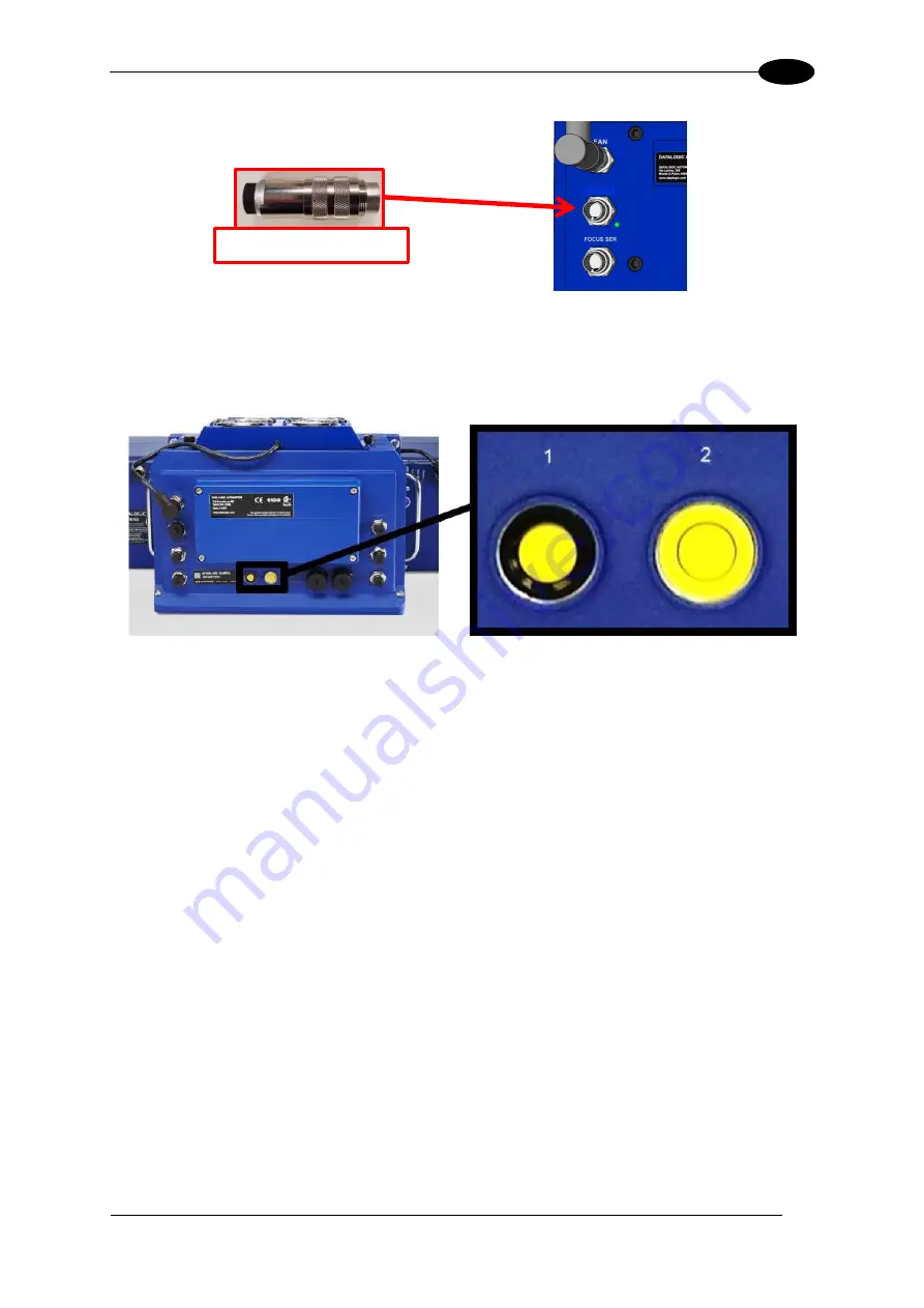
Figure 129: Controller Key
9. With the unit powered up, hold down buttons 1 and 2 at the same time. The STATUS
LED (located to the right of button #2) will blink GREEN and then RED to indicate that the
unit has been defaulted.
Figure 130: Buttons
– Close-up
10. Disconnect the power connection from the camera assembly.
11. Remove the CONTROLLER KEY from the I/O port of the AV7000.
12. Re-attach all of the cables to the camera in their original locations.
13. Apply power to the AV7000 Camera.
14. Connect the browser to any AV7000 in the tunnel EXCEPT the unit being replaced.
15. Navigate to the System Info page.
16.
In the “This Cluster” section of the page the failed camera will show up with the “Delete”
option in the Action column. Note the MAC address of this camera.
17.
The replacement AV7000 will be found in the “Cameras not in the Cluster” portion of the
page.
I/O
CONTROLLER KEY
Summary of Contents for AV7000
Page 1: ...REFERENCE MANUAL AV7000 Linear Camera...
Page 11: ...xi GENERAL VIEW Figure 2 AV7000 Camera Front View Figure 3 AV7000 Camera Back View...
Page 97: ...ELECTRICAL INSTALLATION 85 3 3 11 7 Powered Outputs Figure 86 Powered Outputs NPN PNP...
Page 107: ...E GENIUS 95 4 Click Show to access Contents Index and Search options...
Page 243: ...IMAGING FEATURES 231 5 Ambient Light Ambient light can influence the signal DC level Good Read...
Page 295: ...IMAGING FEATURES 283 5 Figure 137 140mm Short Lens Reading Linear Barcodes...
Page 296: ...AV7000 LINEAR CAMERA REFERENCE MANUAL 284 5 Figure 138 110mm Lens Reading Linear Barcodes...
Page 297: ...IMAGING FEATURES 285 5 Figure 139 90mm Lens Reading Linear Barcodes...
Page 299: ...IMAGING FEATURES 287 5 Figure 141 140mm Short Lens Reading 2D Barcodes...
Page 300: ...AV7000 LINEAR CAMERA REFERENCE MANUAL 288 5 Figure 142 110mm Lens Reading 2D Barcodes...
Page 301: ...IMAGING FEATURES 289 5 Figure 143 90mm Lens Reading 2D Barcodes...
Page 337: ......


