6
DKACT.PS.C20.A1.6D
General
Electronic motor protection relay TI 180 E is a
compact unit with integrated current transform-
ers for motor current measurement.
With TI 180 E a motor can be protected
against:
- thermal overload
- overcurrent (indication by flashing)
- single-phasing and asymmetry
- overtemperature
(thermistor measurement)
Checks
Supply voltage U
s
and frequency must be
identical to that shown on the upper side of the
unit.
Rated motor operating current I
e
must be within
the current range of the relay, 20-180 A (which
can be adjusted down to 2.5-5 A, as described
under “Connection”).
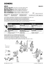
Installation
TI 180 E is designed for wall mounting using
four M5 screws (fig. 1) or on standard rail EN
50022-35
×
7.5. or 35
×
15 (fig. 2).
For dimensions, see fig. 15.
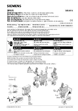
Connection, contactor and electronic
motor protection relay
- conductor bars 037H3027 and three M6
screws onto Danfoss contactor CI 105,
or
- conductor bars 037H3028 and three M6
screws onto Danfoss contactor CI 141/170 EI
(fig. 2A).
Without conductor bars:
Connection to contactor and motor can be
made easier by looping the cable as required
before installing the unit.
TI 180 E as secondary relay
As secondary relay, TI 180 E can also protect
motors with full-load currents if more than 180
A and high-voltage motors for operating
voltages of more than 1000 V.
Recommended current transformer data:
Min. operating voltage =
rated operating voltage of motor
Min. primary current =
operating current of motor
Class and overcurrent factor: 5 P 10
Circuit diagrams
2-phase current measurement (fig. 5)
3-phase current measurement (fig. 6)
Finger protection of main terminals
Use finger protection 037H3246 for TI 180 E/
CI 105 and 037H3409 for TI 180 E/CI 141/CI
170 EI (fig. 2B).
Control connections (fig. 7, A-D)
A: (-)A2, (+)A1: Supply voltage U
s
B:98-97, 96-95: Output contact
C: 3-off (r1,r2,r3) For remote reset module RRM.
Connection (option) shown in
diagram on RRM (fig. 11).
D: 1T1, 2T2 :
Thermistor connection
(overtemperature protection).
If this function is used, first
remove the factory-mounted
resistor RT (1 kohm) and then
connect the PTC temperature
sensors built into the motor to
terminals 1T1 and 2T2.
Settings
Rated operating current of motor (fig. 7, L)
Motor operating current I
e
(See IEC 947-4)
TI 180 E setting: I
e
in amperes or product of I
e
[A] and number of loops (see “Connection”).
Setting range
From 20 to 180 A in steps of 1 A
Setting examples, fig. 8
Example 1
I
e
= 120 A
Slide switches 6 and 8 moved to the right
Contact 6 = 20 A
Contact 8 = 80 A
Basic value = 20 A
I
e
= 120 A
Recom.
Cable cross-section
range (I
e
)
Motor cable
A
mm
2
AWG
20 - 180
Fed straight
4 - 95
10 - 0000
through
10 - 20
2
×
windings
2.5 - 25
14 - 10
fig. 3
5 - 10
4
×
windings
1 - 6
14
fig. 4
2.5 - 5
8
×
windings
0.75 - 2.5
14
Secondary
No. of
Rated current setting
current
windings
5 A
8
20-40 = (2,5-5)
×
8
1 A
40
20-40 = (0,5-1)
×
40
Summary of Contents for TI 180 E
Page 2: ...2 DKACT PS C20 A1 6D Fig 1 Fig 2 Fig 2A Fig 2B Fig 3 Fig 4 Fig 5 Fig 6...
Page 3: ...DKACT PS C20 A1 6D 3 Fig 12 Fig 7 Fig 9 Fig 8 Fig 10 Fig 11...
Page 4: ...4 DKACT PS C20 A1 6D Fig 13...
Page 5: ...DKACT PS C20 A1 6D 5 Fig 14A Fig 14B Fig 15...
Page 31: ...DKACT PS C20 A1 6D 31...
Page 32: ...Danfoss A S AC TMP con 11 2000...