ESIE13-02
Additional Checks for Troubleshooting
159
Part 4 – Troubleshooting
4
3
4
5
4
6.9
Check No.10 - Outdoor Unit: Fan Speed Pulse
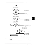
1
Disconnect the connector X106A with the power supply OFF and Operation OFF.
2
Is the voltage between pins 4 and 3 of X106A about 15 VDC after turning the power supply on?
3
Is the voltage between pins 4 and 1 of X106A about 5 VDC?
4
Is the voltage between pins 4 and 7 of X106A about 325 VDC ± 30 VDC?
5
Connect the connector X106A with the power supply OFF and Operation OFF.
6
When making one turn of the upper fan motor by hand after turning the power supply on, is a pulse
(0 and 5 V) generated 2 times between pins 4 and 1 of X106A? (Measure at the contact terminal
on the harness side with the connector connected.)
7
Disconnect the connector X107A with the power supply OFF and Operation OFF.
8
Is the voltage between pins 4 and 3 of X107A about 15 VDC after turning the power supply on?
9
Is the voltage between pins 4 and 1 of X107A about 5 VDC?
10
Is the voltage between pins 4 and 7 of X107A about 325 VDC ± 30 VDC?
11
Connect the connector X107A with the power supply OFF and Operation OFF.
12
When making one turn of the lower fan motor by hand after turning the power supply on, is a pulse
(0 and 5 V) generated 2 times between pins 4 and 1 of X107A?
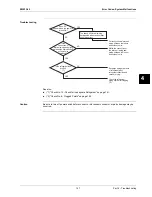
(2) (7): NO
→
Faulty PC board
→
Replace the PC board.
(3) (8): NO
→
Faulty PC board
→
Replace the PC board.
(5)(10): NO
→
Faulty hall IC
→
Replace the DC fan motor.
(2) (3) (5) (7) (8) (10): YES
→
Replace the PC board.
1
2
3
4
5
6
7
Fan speed pulse input (0V and 5V)
0V
15V
GND
NC
NC
250~350V(during operation)
(S2679)

