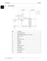
Wiring Diagrams
ESIE13-02
Part 1 – System Outline
38
3
11
4
5
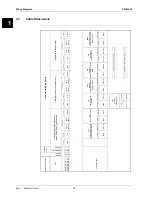
3.3
Cable Dimensions
HP
U Hy
b
ri
d
08.
2013
Ty
pe
Nomi
na
l
capaci
ty
Single pha
se
Tri-pha
se
t
n
er
r
u
C
e
g
atl
o
V
e
s
u
F
t
n
er
r
u
C
e
g
atl
o
V
e
s
u
F
t
n
er
r
u
C
e
g
atl
o
V
Fu
se
HP
U Hy
br
id 5 k
w
4X
HP
U Hy
br
id 8 k
w
H
8
X
HP
U Hy
br
id 8 k
w
H/
K
8
X
outdoor
unit
Cabl
e
t
y
pe
230 V
2 A
3G
1,
5
(≤
35m)
3G
2,
5
(≤3
5
m
)
[1
] S
u
p
p
ly
lin
e
to
th
e
in
d
o
o
r u
n
it
when HT
/N
T
/EVU [
7
] i
s
connect
ed
Cabl
e
t
y
pe
[1
0
)
[4
]
[7
]
[6
]
(8
)
[9
]
1
6
A
(C
)
Ca
ble
dime
ns
ioning Hy
brid
[3] S
u
p
p
ly
to
th
e
g
a
s
b
o
iler
3G
1,
5
(≤1
0
m
)
3G
2,
5
(≤
35m)
1
6
A
(B
)
[2
] S
u
p
p
ly
lin
e
to
th
e
o
u
td
o
o
r u
n
it
Cabl
e
t
y
pe
230 V
2
0
A
(C
)
230 V
3G
2,
5
(≤
35m)
3G
4
(≤7
5
m
)
A
3
1
A
8
1
a
ll H
y
br
id Ty
pe
s
Vol
ta
ge
Cabl
e t
y
pe
Vol
tage
Cabl
e t
y
pe
Vol
ta
ge
Cabl
e t
y
pe
Vol
ta
ge
Cabl
e
t
y
pe
Vol
tage
C
abl
e t
y
pe
Vol
tage
Cabl
e t
y
pe
Vol
tage
Cabl
e t
y
pe
Vol
ta
ge
Cabl
e t
y
pe
if
separate storage tank i
s
i
n
stal
le
d
[1
1
]
optiona
l
D
H
W s
e
ns
or
230 V
SELV 15 V
2 G
0,
75
[1
0
)
C
a
ble
be
tw
e
e
n he
a
t
pum
p s
e
c
tion a
nd ga
s
boile
r s
e
c
tion
[4
]
C
a
ble
be
tw
e
e
n indoor
unit a
nd outdoor
unit
if
addi
ti
onal
outdoor sensor i
n
stal
le
d
[5
]
cab
le
t
o
3 p
o
rt
val
v
e
230 V
G
3 1,
5
5,
1
G
3
5,
1
G
4
V
0
3
2
230 V
[7
]
Optiona
l
c
a
ble
for
be
nfit pow
e
r
s
upply
c
onta
c
t
[6
]
Cab
le t
o
t
h
e u
ser
in
terf
ace
3 G
1,
5
(8
)
Optiona
l
Remo
te
A
larm o
r S
o
la
r
BS
K
[9
]
Optiona
l
outdoor
s
e
n
s
o
r
SELV 15 V
inte
rn
inte
rn
5
7,
0
G
2
V
0
3
2
3
G
0,
75


