CHAMP-AV8 (VPX6-462) H
ARDWARE
U
SER
’
S
M
ANUAL
C
URTISS
-W
RIGHT
3-14
P
ROPRIETARY
826448 V
ERSION
5 M
ARCH
2015
T
ROUBLESHOOTING
V
ERIFY
I
NSERTION
IN
C
HASSIS
Power down the chassis. Make sure that the card is properly seated in the VME chassis.
Because of the five-row backplane, a considerable amount of insertion force is required to seat
the card. Always utilize the injectors to seat the card.
LED D
IAGNOSTICS
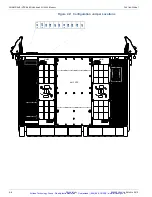
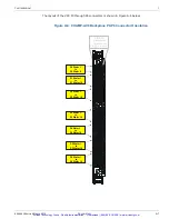
The CHAMP-AV8 has a front panel red Fail LED, eight front panel green Processor Status LEDs
(air-cooled boards only), and eight green surface-mount LEDs. During the board power-up
and reset sequences, the LEDs provide board diagnostic information.
Red Fail LED
The front panel red Fail LED indicates the health status of the CHAMP-AV8 board. The power
sequencing circuitry monitors the backplane 12V and 3.3 V supplies. Once both supplies have
reached their nominal voltage levels, the power sequencing circuitry turns on the on-board
power. When on-board (sequenced) power is applied, the red Fail LED illuminates, indicating
that on-board power is applied. The red Fail LED will remain illuminated as the boot software
executes. Once the board successfully boots and PBIT passes (if enabled), the boot software
then turns off the red Fail LED, indicating that a fault condition has not been detected. If a
fault condition is detected, the boot software will not turn off the red Fail LED. After a board
reset, the red Fail LED will automatically illuminate and remain illuminated until the board has
successfully booted as described above.
Green Front Panel
Processor Status
LEDs
At power-on, the eight front panel green Processor Status LEDs provide board status
information. After the CF-FPGA has been successfully configured, the green Processor Status
LEDs will illuminate. As the boot software initializes each processor node, the software will turn
the respective LED off. Once the board has successfully booted, the LEDs will be turned off
and become available for user control through the board registers. After a board reset, the
green Processor Status LEDs will automatically illuminate and remain illuminated until the boot
software initializes each processor node as described above.
Green Surface
Mount Status
LEDs
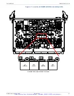
At power-on, the eight green surface mount Status LEDs provide board status information.
After the CF-FPGA has been successfully configured, the green surface mount Status LEDs will
illuminate. After the boot software has initialized all of the processor nodes, the software will
turn off all of the green Status LEDs. Once the board has successfully booted, the LEDs will be
turned off and become available for user control through the board registers.
After a board reset, the green surface mount Status LEDs will automatically illuminate and
stay illuminated until the boot software initializes all of the processor nodes as described
above.
Cross Reference
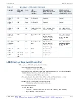
Additional LEDs are provided that show link status and activity for Ethernet 1000Base-BX
and 1000Base-T ports, SATA and PCI express links. See Table 3.7, “Summary of LED
Behavior,” on page 3-15 for a description of LED behavior.
Artisan Technology Group - Quality Instrumentation ... Guaranteed | (888) 88-SOURCE | www.artisantg.com

