C
URTISS
-W
RIGHT
P
RODUCT
O
VERVIEW
826448 V
ERSION
5 M
ARCH
2015
P
ROPRIETARY
1-29
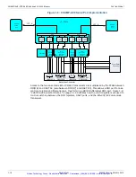
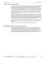
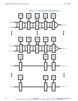
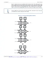
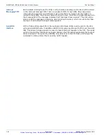
Figure 1.14 below shows how each GROUP_INTx line feeds to each of the 13 IRQ outputs. Each
of the 16 GROUP_INTx lines can be individually enabled to feed into a particular IRQ via a MST
Enable Register. After the enable register, each bit status is sampled and fed to a MST Status
Register. After this stage, all enabled GROUP_INTx bits are combined into the single IRQx
output, such that if any enabled GROUP_INTx bit is asserted, the IRQx line is also asserted.
Figure 1.14: Interrupt Routing Block (Part B)
Note
IRQ0 and IRQ1 can only have the vector input groups SRC7-0 assigned to them. The scalar
groups SRC15-8 cannot be assigned to these IRQs.
MST
Enable
Reg
R/W
MST
Source
Reg
RO
IRQ0
GROUP_INT0
GROUP_INT7
MST
Enable
Reg
R/W
MST
Source
Reg
RO
IRQ2
GROUP_INT0
GROUP_INT15
MST
Enable
Reg
R/W
MST
Source
Reg
RO
IRQ12
GROUP_INT0
GROUP_INT15
MST
Enable
Reg
R/W
MST
Source
Reg
RO
IRQ1
GROUP_INT0
GROUP_INT7
Artisan Technology Group - Quality Instrumentation ... Guaranteed | (888) 88-SOURCE | www.artisantg.com

