C
URTISS
-W
RIGHT
1
826448 V
ERSION
5 M
ARCH
2015
P
ROPRIETARY
A-3
C
ONNECTOR
O
VERVIEW
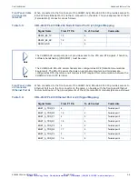
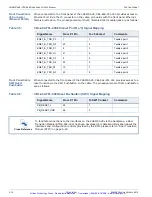
This appendix provides the interface pinout information for each of the connectors on the
CHAMP-AV8, and explains how you can use the Pinout Configurator utility to generate custom
pinout tables based on the type and location of any XMC modules you choose to install on the
basecard. The corresponding VPX Backplane interface pin assignments are also provided.
B
ACKPLANE
VPX C
ONNECTORS
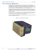
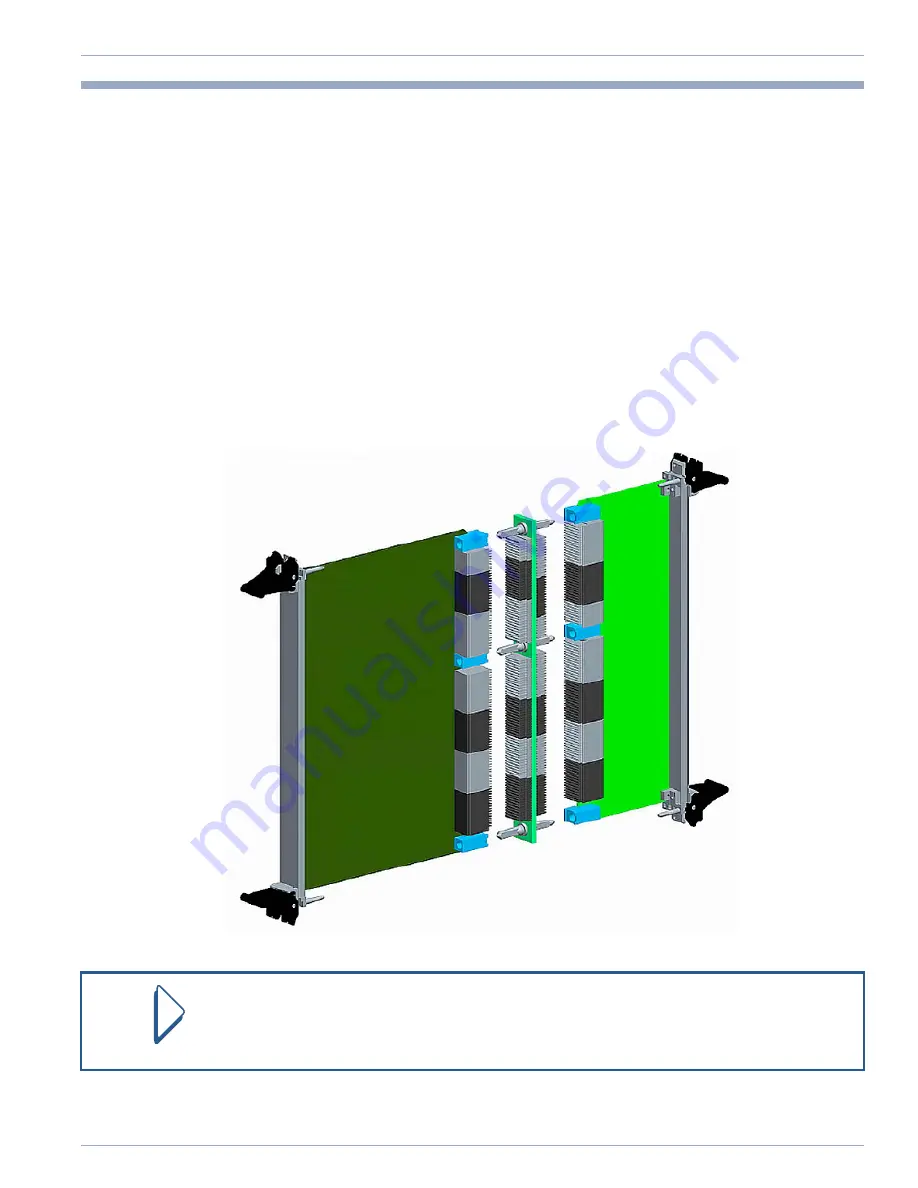
The industry VITA 46 series standards define the details of VPX system connectors from the
front plug-in module to the backplane front-side, backplane rear-side, and Rear Transition
Module (RTM), including mechanical dimensions, part numbers, and electrical pin definitions.
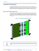
Figure A.1 below provides an illustration of how the VPX connectors are mated from a system
point of view.
Figure A.1: VPX System Connectors Overview
Note
A Rear Transition Module (RTM) is available to facilitate connectivity with the CHAMP-AV8.
Detailed information about the RTM is provided in “Rear Transition Module (RTM)” on page
A-52.
Artisan Technology Group - Quality Instrumentation ... Guaranteed | (888) 88-SOURCE | www.artisantg.com

