Operator’s manual
A 222
97
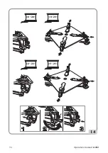
- Adjust the position of the shovel through the pin (1 fig. 10A) based on the size of the tire.
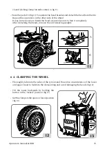
- Position the wheel as shown in fig.11 and bring the bead breaker shoe to the edge of the rim.
IMPORTANT:
During the bead breaking operation, you are advised to keep the table top
closed (locking clamp towards center) (A fig.11).
- Press the pedal 10 (fig.11) to operate the bead breaker and detach the bead from
the rim. Repeat this operation on the other side of the wheel.
It may be necessary to break the bead at several points to free it completely.
After detaching the beads, remove the old balancing weights.
- Thoroughly lubricate the sides of the tyre around the entire circumference of the lower and
upper bead to facilitate the demounting and avoid damaging the beads (fig.12).
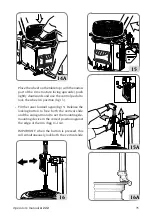
- Tilt the tower backwards by holding the knob in the “locked” position (Fig. 13).
- Set the clamps to the open or closed position (fig.14).
Place the wheel on the table top (with the narrow part of the rim structure facing upwards),
push lightly downwards and use the control pedal
to lock the wheel in position
(fig.14a).
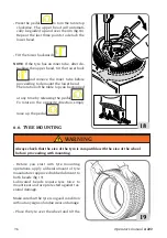
- Tilt the tower forward again
(fig.15).
Release the locking knob to free both the vertical slide and the swing arm (fig.15a) and to set
the mounting/demounting device in the correct position against the edge of the rim (fig.16).
IMPORTANT
: Operating the knob, this will simultaneously lock both the vertical slide and the
swing arm, with the mounting/demounting vertical slide moving slightly up and away from
the edge of the rim (fig.16a).
This space between the rim and the vertical slide will be maintained for as long as the knob
is in the locking position.
The operator can tilt the tower freely (eg. when demounting wheels of the same size) without
repositioning the vertical slide.
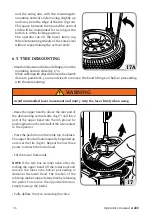
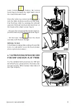
- Insert and position the bead lifting tool on the mounting vertical slide (fig.17).
When working with alloy wheels or wheels with delicate paintwork, you are advised to remove
the bead lifting tool before proceeding with the demounting.
Grip the lever firmly when using.
WARNING
- Raise the upper bead to above the rear part of the demounting vertical slide (fig.17a) and
force part of the upper bead into the rim groove by pushing down on the side wall of the
tyre nearest to the operator.
Summary of Contents for A 222
Page 59: ...Manuale d uso A 222 59 A 222 ...
Page 60: ...60 Manuale d uso A 222 A 222 VERSIONE TI ...
Page 61: ...Manuale d uso A 222 61 A 222 CON MOTORE AD ARIA ...
Page 62: ...62 Manuale d uso A 222 A 222 VERSIONE TI CON MOTORE AD ARIA ...
Page 63: ...Note 63 ...
Page 121: ...Operator s manual A 222 121 A 222 ...
Page 122: ...122 Operator s manual A 222 A 222 TI VERSION ...
Page 123: ...Operator s manual A 222 123 A 222 WITH AIR MOTOR ...
Page 124: ...124 Operator s manual A 222 A 222 TI VERSION WITH AIR MOTOR ...
Page 125: ... 125 ...
Page 183: ...Utilisation et entretien A 222 183 A 222 ...
Page 184: ...184 Utilisation et entretien A 222 A 222 VERSION TI ...
Page 185: ...Utilisation et entretien A 222 185 A 222 MOTEUR PNEUMATIQUE ...
Page 186: ...186 Utilisation et entretien A 222 A 222 VERSION TI MOTEUR PNEUMATIQUE ...
Page 187: ...Note 187 ...
Page 245: ...Betriebs und Wartungsanleitung A 222 245 A 222 ...
Page 246: ...246 Betriebs und Wartungsanleitung A 222 A 222 VERSION TI ...
Page 247: ...Betriebs und Wartungsanleitung A 222 247 A 222 DRUCKLUFTMOTOR ...
Page 248: ...248 Betriebs und Wartungsanleitung A 222 A 222 VERSION TI DRUCKLUFTMOTOR ...
Page 249: ...Hinweise 249 ...
Page 307: ...Uso y mantenimiento A 222 307 A 222 ...
Page 308: ...308 Uso y mantenimiento A 222 A 222 VERSIÓN TI ...
Page 309: ...Uso y mantenimiento A 222 309 A 222 MOTOR NEUMÁTICO ...
Page 310: ...310 Uso y mantenimiento A 222 A 222 VERSIÓN TI MOTOR NEUMÁTICO ...
Page 311: ...Notas 311 ...

