Switch S1
Master
HeX
DeC
0
0
1
1
2
2
3
3
Switch S2
Slave
HeX
DeC
0
0
1
1
2
3
4
4
5
5
6
7
8
8
9
9
A
B
C
12
D
13
e
F
S2
S1
X1
X10
DEVICE ID
AMP
NET
IN
OUT
Axis A
J7
Axis B
RoHS
Xenus
PLUS
2-Axis
MACRO
XM2
Rev 01
Copley Controls, 20 Dan Road, Canton, MA 02021, USA
16-01419
Rev A
Page 5 of 34
Macro coMMunIcatIons
IndIcators: drIVe state
MACRO (Motion And Control Ring Optical) is a non-proprietary communications network that uses optical fibre or copper cabling and supports bit-rates
up to 125 Mb/sec. The Xenus Plus MACRO (XM2) uses the optical fibre interface and operates typically as a torque drive. Velocity drive mode is also
supported.
More information on MACRO can be found on the organization web-site: http://www.macro.org/index.html
MACRo ConneCtionS
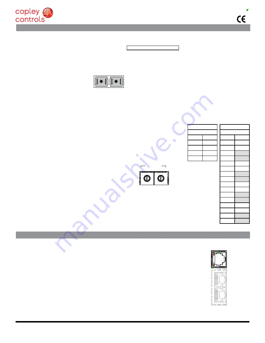
Dual SC sockets accept standard optical fiber. The IN port connects to a master, or to the OUT port of a device that is ‘upstream’, between the XM2 and
the master. The OUT port connects to ‘downstream’ nodes. If XM2 is the last node on a network, only the IN port is used. No terminator is required on
the oUt port.
J7: M
ACRo PoRt
Duplex type SC
optical fiber connector
MACRo ADDReSS
A PMAC card can hold up to four MACRO IC’s each of which is a master on a MACRO
ring. each master iC can address 16 stations (nodes, slaves) enabling the addressing of up to
64 devices on a ring. of these, 32 can be motion devices such as XM2.
A node address is an 8-bit value with bits 7~4 addressing the master IC and bits 3~0
addressing the slave. Switch S1 is set to select the master iC to which the Xenus will be
linked. The four possible values for this setting are 0,1,2, and 3.
As a MACRo station or node the XM2 has eight available addresses as a motion con-
trol device. These are 0,1,4,5,8,9,12, & 13. Addresses 2,3,6,7,10, & 11 are for I/O stations
and addresses 14 & 15 are reserved. The table shows the available selections for S2. Boxes
greyed-out are invalid selections and have no function.
The switch positions are numbered in hexadecimal. The chart shows these positions with the
slave address shown in decimal.
Example: Configure the XM2 as node 36 (0x24)
the XM2 will be node 4 controlled by master iC 2 on the PMAC
S1 = 2 (Master IC 2)
S2 = 4 (Slave address)
the S1 settings are in multiples of 16 (2
4
), so 2 X 16 = 32.
the S2 settings are read directly equal 4.
This produces the node address of 2 x 16 + 4 = 36.
MACRo node
Address Switches
AXiS leDS: DRiVe StAtUS
A bi-color lED gives the state of each axis. Colors do not alternate, and can be solid ON or blinking.
When multiple conditions occur, only the top-most condition will be displayed.
When that condition is cleared the next one below will shown.
1) Red/Blinking
= latching fault. Operation will not resume until drive is Reset.
2) Red/Solid
= Transient fault condition. Drive will resume operation when
the condition causing the fault is removed.
3) Green/Double-Blinking = STO circuit active, drive outputs are Safe-Torque-Off
4) Green/Slow-Blinking
= Drive OK but NOT-enabled. Will run when enabled.
5) Green/Fast-Blinking
= Positive or Negative limit switch active.
Drive will only move in direction not inhibited by limit switch.
7) Green/Solid
= Drive OK and enabled. Will run in response to
MACRo commands or analog input.
latching Faults
Default
optional (programmable)
• Short circuit (Internal or external)
• Over-voltage
• Drive over-temperature
• Under-voltage
• Motor over-temperature
• Motor Phasing Error
• Feedback Error
• Command Input Fault
• Following Error


