Signal
Pins
Brake A
J5-3
Brake B
J5-2
input
State
Condition
OUT5
Hi
Output transistor is ON, current flows
lo
Output transistor is OFF, no current flows
BRk-A,B
OUT6,7
Hi
output transistor is oFF
Brake is un-powered and locks motor shaft
Motor cannot move
Brake state is Active
lo
output transistor is on
Brake is powered, releasing motor shaft
Motor is free to move
Brake state is NOT-Active
Signal
Pins
[OUT5+]
J9-23
[OUT5-]
J9-14
[oUt6]
J5-3
[OUT7]
J5-2
[OUTn-]
300mA
max
* at 24 Vdc
Vdc
J9
[OUTn+]
1
80
Ω
min*
36V
SSR
+
J5
B Brk
A Brk
Axis A
Brake
Axis B
Brake
5
4
24V
+24
+24
*
24V RTN
2
3
1
i
+
0
RoHS
Xenus
PLUS
2-Axis
MACRO
XM2
Rev 01
Copley Controls, 20 Dan Road, Canton, MA 02021, USA
16-01419
Rev A
Page 22 of 34
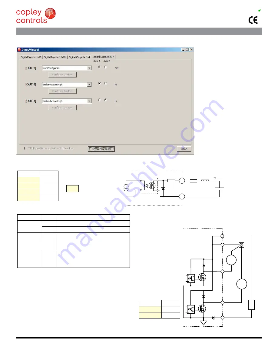
CME2 Default Setting for Brake Outputs [OUT6,7] is “Brake - Active HI”
Active = Brake is holding motor shaft (i.e. the
Brake is Active)
Motor cannot move
No current flows in coil of brake
CME2 I/O line States shows Output 6 or 7 as HI
BRk output voltage is Hi (24V), MoSFet is oFF
Servo drive output current is zero
Servo drive is disabled, PWM outputs are off
Inactive = Brake is not holding motor shaft (i.e. the
Brake is Inactive)
Motor can move
Current flows in coil of brake
CME2 I/O line States shows Output 6 or 7 as lO
BRk output voltage is lo (~0V), MoSFet is on
Servo drive is enabled, PWM outputs are on
Servo drive output current is flowing
CME2 SCREEN FOR OUTPUTS [OUT5~7]
oUtPUt DAtA
[OUT5]
[BRk-A,B]
[OUT6~7]
Hi/lo DeFinitionS: oUtPUtS
[OUT5~7] SIGNAlS
+24V
+30Vmax
+24V typical
cMe2 & outputs 5~7 connectIons
There should be only one
conductor in each position
of the J5 connector. If
brakes are to be wired
directly to J5 for their
24V power, use a double
wire ferrule for J5-4.
Information for ferrules
can be found on page 30.
*


