Table 24: Operating Temperature and Humidity Recommendations
0 degrees C to +55 degrees C
32 degrees F to +131 degrees F
Operating Temperature
20 percent to 80 percent, non-condensing
Operating Humidity
Mounting Options
There are two options for mounting the chassis in a standard equipment rack or telecommunications cabinet:
•
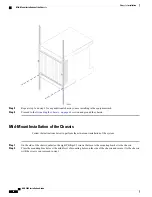
Flush Mount
: In this configuration, the flanges of the mounting brackets are flush with the front of the
chassis. This is the default configuration as shipped as is commonly used with 4-post racks and equipment
cabinets. Refer to
Flush Mount Installation of the Chassis, on page 57
.
•
Mid-mount
: In this configuration, the flanges of the mounting brackets are recessed from the front of
the chassis. This configuration is required when mounting the chassis in a 2-post rack. To do this, install
the mounting brackets toward the middle of the chassis on either side. Refer to
of the Chassis, on page 58
.
Weight Considerations
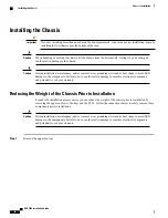
The shipping weight of the chassis is approximately 160 pounds (72.57 kg). Please consider the following
recommendations before proceeding:
•
If available, use an equipment lift to lift and move the chassis during the installation process.
•
If no lift is available, reduce the weight according to the instructions in the
Chassis Prior to Installation, on page 54
. These procedures reduces the weight of the chassis to
approximately 125 lbs. (56.7 kg).
•
At least two people are required to perform the installation. These individuals should be physically able
to lift and control the weight of the chassis.
•
When lifting any heavy object, it is important to remember to bend at the knees and lift with your legs.
Bending at the waist and lifting with your back could cause personal injury.
Unpacking the ASR 5000 Chassis
Before unpacking the chassis, use a pallet jack to move the container as close to the final installation site
as possible.
Important
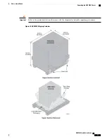
The chassis ships in a wooden container that is 28.25 in. (64.135cm) wide by 36.75 in. (93.35cm) high by
33.75 in. (85.75cm) deep. The container consists of an upper and lower section. The upper section forms the
sides and top of the container. The lower section serves as the bottom of the container. The upper and lower
ASR 5000 Installation Guide
51
Chassis Installation
Mounting Options
Summary of Contents for ASR 5000
Page 16: ...ASR 5000 Installation Guide xvi About this Guide Contacting Customer Support ...
Page 64: ...ASR 5000 Installation Guide 48 Installation Procedure Overview Laser Notice ...
Page 100: ...ASR 5000 Installation Guide 84 Line Card Installation Installing the XGLC ...
Page 122: ...ASR 5000 Installation Guide 106 Cabling the Fast Ethernet 10 100 Line Card FLC2 Interfaces ...
Page 206: ...ASR 5000 Installation Guide 190 Removing and Installing SMC PC Cards Removing PC Cards ...
Page 212: ...ASR 5000 Installation Guide 196 Replacing the Chassis Air Filter Installing the Air Filter ...
Page 220: ...ASR 5000 Installation Guide 204 Replacing a Power Filter Unit What to do with the Failed PFU ...
Page 266: ...ASR 5000 Installation Guide 250 Safety Electrical and EMC Certifications Korean EMC ...
Page 270: ...ASR 5000 Installation Guide 254 Environmental Specifications Chassis Air Flow ...

