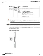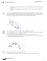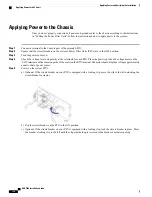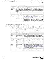
The following figure provides a flowchart that explains each step in the startup process.
Figure 51: Boot Process Flowchart
Step 1
When power is first applied to the chassis, or after a reboot, only the SMC in slots 8 and 9 receive power. Therefore, the
SMCs are the first cards to boot and their LEDs are the first to light up. Once the system confirms that cards are located
in slots 8 and 9, power is quickly applied to the SPIOs in slots 24 and 25.
Step 2
During the startup process, each card performs a series of Power-On Self Tests (POSTs) to ensure that the hardware is
ASR 5000 Installation Guide
134
Applying Power and Verifying the Installation
Understanding the System Boot Process
Summary of Contents for ASR 5000
Page 16: ...ASR 5000 Installation Guide xvi About this Guide Contacting Customer Support ...
Page 64: ...ASR 5000 Installation Guide 48 Installation Procedure Overview Laser Notice ...
Page 100: ...ASR 5000 Installation Guide 84 Line Card Installation Installing the XGLC ...
Page 122: ...ASR 5000 Installation Guide 106 Cabling the Fast Ethernet 10 100 Line Card FLC2 Interfaces ...
Page 206: ...ASR 5000 Installation Guide 190 Removing and Installing SMC PC Cards Removing PC Cards ...
Page 212: ...ASR 5000 Installation Guide 196 Replacing the Chassis Air Filter Installing the Air Filter ...
Page 220: ...ASR 5000 Installation Guide 204 Replacing a Power Filter Unit What to do with the Failed PFU ...
Page 266: ...ASR 5000 Installation Guide 250 Safety Electrical and EMC Certifications Korean EMC ...
Page 270: ...ASR 5000 Installation Guide 254 Environmental Specifications Chassis Air Flow ...


