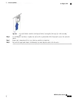
When the system boots up, all packet processing cards enter standby mode, which means that the cards are
available for use but offline. Installed components are made active through the software configuration process.
Cards that are not configured to enter active mode, which brings them online, remain in standby mode as
redundant components. Packet processing cards that normally operate in standby mode do not require line
cards to be installed directly behind them, as these line cards are not used.
In the event of packet processing card failure, tasks are migrated from the active packet processing card to
the standby card. The line card installed behind the packet processing card that was formerly active maintains
the interfaces to the external network equipment. Redundancy Crossbar Cards (RCCs) provide a path for
signalling and data traffic between the line card and the now active packet processing card.
For additional information about RCCs, refer to
Line Card Installation
in this guide.
Important
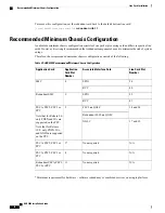
Recommended Minimum Chassis Configuration
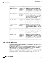
The recommended minimum chassis configuration for application cards, including redundancy, is as follows:
Card State
Card
Slot Number
Active
SMC
8
Standby
SMC
9
Active
PSC2 or PSC3
2 and 4 (see Note 1)
2, 3 and 4 (see Note 2)
Standby
PSC2 or PSC3
11 (see Notes 1 and 2)
Notes:
1. Minimum requirement for hardware redundancy.
2. Minimum requirement for ha software redundancy, MME service, SGSN service, as well as
combined services on a single platform.
Install additional cards in the remaining chassis slots as required.
If you use the session recovery feature, a minimum of three active packet processing cards and one standby
(redundant) packet processing card are required.
Installing Application Cards
The installation procedure is identical for all application cards. This section provides the instructions for
installing application cards in the chassis.
ASR 5000 Installation Guide
69
Application Card Installation
Recommended Minimum Chassis Configuration
Summary of Contents for ASR 5000
Page 16: ...ASR 5000 Installation Guide xvi About this Guide Contacting Customer Support ...
Page 64: ...ASR 5000 Installation Guide 48 Installation Procedure Overview Laser Notice ...
Page 100: ...ASR 5000 Installation Guide 84 Line Card Installation Installing the XGLC ...
Page 122: ...ASR 5000 Installation Guide 106 Cabling the Fast Ethernet 10 100 Line Card FLC2 Interfaces ...
Page 206: ...ASR 5000 Installation Guide 190 Removing and Installing SMC PC Cards Removing PC Cards ...
Page 212: ...ASR 5000 Installation Guide 196 Replacing the Chassis Air Filter Installing the Air Filter ...
Page 220: ...ASR 5000 Installation Guide 204 Replacing a Power Filter Unit What to do with the Failed PFU ...
Page 266: ...ASR 5000 Installation Guide 250 Safety Electrical and EMC Certifications Korean EMC ...
Page 270: ...ASR 5000 Installation Guide 254 Environmental Specifications Chassis Air Flow ...


