C H A P T E R
6
Cabling the Switch Processor Input/Output Line
Card
This chapter provides information on the Switch Processor Input/Output (SPIO) line card interfaces and
instructions for installing the cables.
Class 1 Laser Compliance Notice
Because of the SFP interfaces, this product has been tested and found
to comply with the limits for Class 1 laser devices for IEC825, EN60825, and 21CFR1040 specifications.
Important
This chapter includes the following sections:
•
•
Connecting to the Management LAN, page 88
•
Connecting to the Serial Console Port, page 91
•
Connecting to a BITS Timing Source, page 95
•
Connecting to the CO Alarm Interface, page 97
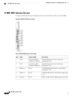
SPIO Interfaces
The SPIO is available with the following types of interfaces:
•
Two Gigabit Ethernet, fiber optical (SFP)
•
Two 1000Base-T Ethernet, copper (RJ-45)
•
One RS-232 interface (RJ-45)
•
One Central Office alarms (10-pin Molex))
•
One BITS (BNC or 3-pin connector)
ASR 5000 Installation Guide
85
Summary of Contents for ASR 5000
Page 16: ...ASR 5000 Installation Guide xvi About this Guide Contacting Customer Support ...
Page 64: ...ASR 5000 Installation Guide 48 Installation Procedure Overview Laser Notice ...
Page 100: ...ASR 5000 Installation Guide 84 Line Card Installation Installing the XGLC ...
Page 122: ...ASR 5000 Installation Guide 106 Cabling the Fast Ethernet 10 100 Line Card FLC2 Interfaces ...
Page 206: ...ASR 5000 Installation Guide 190 Removing and Installing SMC PC Cards Removing PC Cards ...
Page 212: ...ASR 5000 Installation Guide 196 Replacing the Chassis Air Filter Installing the Air Filter ...
Page 220: ...ASR 5000 Installation Guide 204 Replacing a Power Filter Unit What to do with the Failed PFU ...
Page 266: ...ASR 5000 Installation Guide 250 Safety Electrical and EMC Certifications Korean EMC ...
Page 270: ...ASR 5000 Installation Guide 254 Environmental Specifications Chassis Air Flow ...


