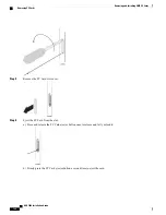
Step 2
Slide the PFU assembly into the PFU bay until it is flush against the chassis.
Step 3
Use a Phillips #2 screwdriver to tighten each of the four screws on the PFU to secure it to the chassis.
Step 4
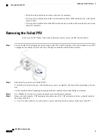
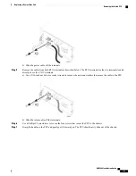
Use a Phillips #2 screwdriver to remove the plastic cover from the power terminals.
Each of the four power terminals is shipped with one nut and two washers. The 165A PFU has one lock-washer and one
flat washer.
To avoid electric shock, ensure that the power source is off before attaching power cables to the PFU(s) installed in the
chassis.
Spannungsversorgung abschalten vor Anschluss der Kabel an die Netzteile, um einen elektrischen Schlag zu vermeiden.
ASR 5000 Installation Guide
201
Replacing a Power Filter Unit
Installing the Replacement PFU
Summary of Contents for ASR 5000
Page 16: ...ASR 5000 Installation Guide xvi About this Guide Contacting Customer Support ...
Page 64: ...ASR 5000 Installation Guide 48 Installation Procedure Overview Laser Notice ...
Page 100: ...ASR 5000 Installation Guide 84 Line Card Installation Installing the XGLC ...
Page 122: ...ASR 5000 Installation Guide 106 Cabling the Fast Ethernet 10 100 Line Card FLC2 Interfaces ...
Page 206: ...ASR 5000 Installation Guide 190 Removing and Installing SMC PC Cards Removing PC Cards ...
Page 212: ...ASR 5000 Installation Guide 196 Replacing the Chassis Air Filter Installing the Air Filter ...
Page 220: ...ASR 5000 Installation Guide 204 Replacing a Power Filter Unit What to do with the Failed PFU ...
Page 266: ...ASR 5000 Installation Guide 250 Safety Electrical and EMC Certifications Korean EMC ...
Page 270: ...ASR 5000 Installation Guide 254 Environmental Specifications Chassis Air Flow ...


