B-2
CP2210 Service Manual
020-100556-04 Rev. 1 (01-2012)
Appendix B: Overfill
5. Turn the screw 1/4” of a turn in the same direction.
NOTE:
Each turn must be exactly 1/4” of a turn to
ensure accuracy.
If there is no shadow at the top of the image turn the screw another 1/4” in the same
direction.
6. Although it is hard to see find the top edge of the DMD output, typically this is where the edge of the
screen is assuming the integrator is aligned.
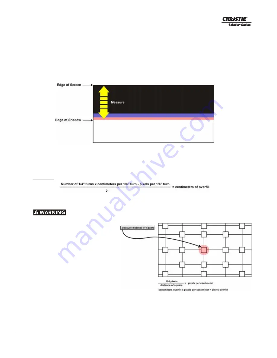
7. Use a ruler to measure from the top edge of the DMD output to the point where there is no discoloration or
fading of the white image (
Figure B-2
). This will give you the centimeters that the output beam moved.
Figure B-2Adjusting Overfill
8. Subtract the pixels per 1/4” turn value (Step 7) from the number of pixels that the light beam traveled (Step
3) and dived by two. This will give you the centimeters of overfill on the top and bottom.
9. Repeat Steps 1-8 for the left and right overfill.
Equation:
B.1.2 Converting Centimeters to Pixels
Overfill should be adjusted to 15 pixels on each side.
1. Display a 17L-Point test pattern by
accessing the
Test Patterns
menu via
the TPC and selecting
DC2K 17L
Point
.
NOTE:
This test pattern is
included with DLP cinema releases
11.1.33 or higher.
2. Use a ruler to measure the width of a
square on the test pattern (
Figure B-
3
). This box is 100 pixels wide.
3. Repeat the entire procedure for
horizontal overfill. The travel per 1/4”
turn is different every time.
4. Once both vertical and horizontal
overfill is completed re-align the integrator and fold mirror. For details, refer to
3.3 Integrator Alignment,
on page 3-3
and
3.2 Fold Mirror Alignment, on page 3-2
.
Figure B-3 Test Pattern


