1A -34 HEATER A N D AIR C O N D IT I O N I N G
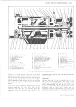
Fig. 38--Accumulator
in a correctly designed system, no liquid can get to the
compressor.
In an actual accumulator, there is some entrained liquid
in the vapor stream to the compressor. The measure of a
good accumulator is how well it separates vapor from
liquid and how little entrained liquid is released to the
compressor. Also, in an actual accumulator, an oil bleed
hole is required to prevent trapping of oil in the bottom
of the accumulator; this oil bleed hole bleeds some liquid
refrigerant as well.
Therefore, flow out of the accumulator to the compressor
consists mostly of vapor with the addition of entrained
liquid and liquid flow through the oil bleed hole.
A bag of desiccant (dehydrating agent) is located in the
base of the accumulator as a moisture collecting device.
NOTE: There is no sight glass in the
accumulator clutch cycle system.
Expansion Tube--C-K Models
Expansion tube flow rate depends on pressure difference
and on subcooling; however, the flow rate is more
sensitive to subcooling.
Fig. 39-Expansion Tube
The expansion tube is located in the enlarged portion of
the evaporator inlet line.
Thermostatic Switch
System temperature is controlled by running the
compressor intermittently, automatically turning it on
and off as necessary to maintain proper temperatures.
The compressor is started and stopped through the use of
an electro-magnetic clutch and a thermostat affected by
variations in temperature.
The thermostatic switch incorporates a metallic tube
which contains a highly expansive gas. This tube is
inserted into the evaporator core (C-K Four-Season
System) or is located in the air stream as it leaves the
evaporator (all other systems). The tube leads to a
bellows operated switch. As air temperature rises, the gas
inside the tube expands, travels through the tube to the
bellows and closes the electrical switch which engages the
compressor clutch.
As soon as the compressor starts running, the
temperature begins to go down. As the air being cooled
gets colder, the gas in the thermostatic tube begins to
reduce the pressure on the switch bellows. This allows the
switch contacts to open and the compressor clutch
disengages.
Low Refrigerant Charge Protection System
C-K Models
The compressor discharge pressure switch performs the
function of shutting off the compressor when it senses
low refrigerant pressure. The switch is located in the
evaporator inlet line (high pressure). The switch
electrically is wired in series between the compressor
clutch and the master switch on the control. When the
switch senses low pressure it breaks contact and opens
the circuit to the compressor clutch, thus shutting off the
A/C system and preventing compressor failure or
seizure.
“ O ” RING
\
INLET
LIGHT DUTY TRUCK SERVICE MANUAL
Summary of Contents for Light Duty Truck 1973
Page 1: ......
Page 4: ......
Page 6: ......
Page 53: ...HEATER AND AIR CONDITIONING 1A 27 LIGHT DUTY TRUCK SERVICE MANUAL...
Page 115: ...LIGHT DUTY TRUCK SERVICE M A N U A L HEATER AND AIR CONDITIONING 1A 89...
Page 123: ...BODY 1B 3 Fig 6 Typical 06 Van LIGHT DUTY TRUCK SERVICE MANUAL...
Page 149: ...BODY 1B 29 Fig 84 Body Mounting 06 Fig 85 Body Mounting 14 LIGHT DUTY TRUCK SERVICE MANUAL...
Page 171: ...LIGHT DUTY TRUCK SERVICE M A N U A L Fig 2 Frame Horizontal Checking Typical FRAME 2 3...
Page 173: ...LIGHT DUTY TRUCK SERVICE M A N U A L Fig 4 10 30 Series Truck Frame FRAME 2 5...
Page 174: ...2 6 FRAME LIGHT DUTY TRUCK SERVICE MANUAL Fig 5 Underbody Reference Points G Van...
Page 185: ...FRONT SUSPENSION 3 11 Fig 16 Toe out on Turns LIGHT DUTY TRUCK SERVICE MANUAL...
Page 224: ......
Page 266: ......
Page 351: ...ENGINE 6 15 Fig ID Sectional View of Eight Cylinder Engine LIGHT DUTY TRUCK SERVICE MANUAL...
Page 375: ...EN G IN E 6 39 LIGHT DUTY TRUCK SERVICE MANUAL...
Page 376: ...6 4 0 ENGINE LIGHT DUTY TRUCK SERVICE MANUAL...
Page 377: ...ENG IN E 6 41 LIGHT DUTY TRUCK SERVICE MANUAL...
Page 378: ...LIGHT DUTY TRUCK SERVICE MANUAL Fig 37L K Series Engine Front Mount 6 42 ENG INE...
Page 400: ...6 6 4 ENG INE LIGHT DUTY TRUCK SERVICE MANUAL...
Page 401: ...ENG IN E 6 65 LIGHT DUTY TRUCK SERVICE MANUAL...
Page 402: ...6 6 6 ENGINE LIGHT DUTY TRUCK SERVICE MANUAL...
Page 403: ...E NG IN E 6 67 Fig 36V C Series Engine Mounts LIGHT DUTY TRUCK SERVICE MANUAL...
Page 410: ......
Page 423: ...EN G IN E C OOLING 6K 13 Fig 16 Overheating Chart LIGHT DUTY TRUCK SERVICE MANUAL...
Page 424: ...6 K 1 4 ENG INE COOLING Fig 17 Coolant Loss Chart LIGHT DUTY TRUCK SERVICE MANUAL...
Page 456: ...6M 32 ENGINE FUEL Fig K15 Accelerator Controls G Van L 6 LIGHT DUTY TRUCK SERVICE MANUAL...
Page 492: ......
Page 512: ...Fig 18e Vacuum Advance Diagram V8 Engine...
Page 516: ...6 T 2 4 E M IS S IO N CONTROL SYSTEMS LIGHT DUTY TRUCK SERVICE MANUAL...
Page 528: ......
Page 590: ......
Page 593: ...CLUTCHES MANUAL TRANSMISSIONS 7M 3 LIGHT DUTY TRUCK SERVICE MANUAL...
Page 598: ...7M 8 CLUTCHES MANUAL TRANSMISSIONS LIGHT DUTY TRUCK SERVICE MANUAL...
Page 642: ......
Page 654: ......
Page 743: ...FUEL TANKS AND EXHAUST 8 13 LIGHT DUTY TRUCK SERVICE MANUAL...
Page 744: ...8 14 FUEL TANKS AND EXHAUST LIGHT DUTY TRUCK SERVICE MANUAL...
Page 760: ...8 30 FUEL TANKS AND EXHAUST Fig 40 Exhaust Pipe P Models LIGHT DUTY TRUCK SERVICE MANUAL...
Page 761: ...FUEL TANKS AND EXHAUST 8 31 LIGHT DUTY TRUCK SERVICE MANUAL...
Page 763: ...FUEL TANKS AND EXHAUST 8 33 LIGHT DUTY TRUCK SERVICE MANUAL...
Page 766: ......
Page 832: ...LIGHT DUTY TRUCK SERVICE MANUAL Fig 106 Power Steering Pump Mounting Typical 9 66 STEERING...
Page 833: ...PUMP ASSEMBLY STEERING GEAR TYPICAL SMALL V8 TYPICAL LARGE V8 STEERING 9 67...
Page 861: ...STEERING 9 95 Fig 134 Power Steering Pump Leakage LIGHT DUTY TRUCK SERVICE MANUAL...
Page 864: ......
Page 876: ......
Page 886: ...11 10 CHASSIS SHEET METAL LIGHT DUTY TRUCK SERVICE MANUAL...
Page 891: ...ELECTRICAL BODY AND CHASSIS 12 5 LIGHT DUTY TRUCK SERVICE MANUAL...
Page 934: ......
Page 942: ......
Page 970: ......
Page 972: ......
Page 974: ......
Page 976: ...V...
Page 978: ......
Page 979: ......


