E M I S S I O N C O N T R O L S Y S T E M S
6 T - 1 1
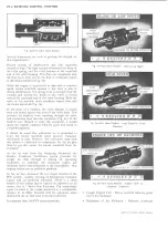
CEC SO LEN O ID
IDLE STOP SO LEN O ID
Fig. 5d—L-6 Idle Stop and CEC Solenoids
COMPONENT DESCRIPTION
Idle Stop Solenoid
The idle stop solenoid is a two position electrically
operated control, used to provide a predetermined
throttle setting (fig. 5d). In the energized position
(plunger extended) the plunger contacts the carburetor
throttle lever and prevents full closing of the carburetor
throttle plates. This fast idle control when de-energized
(plunger retracted) allows throttle plates to close beyond
the normal idle position; thereby shutting off air supply
and in essence starving the engine so that it will shut
down without dieseling. The idle stop solenoid is attached
to the carburetor so that the plunger, when extended,
contacts the throttle lever.
CEC SOLENOID
The CEC solenoid (fig. 5d) is a two-position electrically
operated control, which serves a dual function in the
TCS system. In the de-energized position the spring
loaded plunger closes the vacuum supply port to the
distributor advance unit and opens the air vent to the
advance unit. In the energized position the plunger is
extended to contact the carburetor throttle lever and to
open the vacuum port to the distributor and to shut off
the air vent. The solenoid is bracket-attached to the
carburetor so that the plunger, when extended, contacts
the throttle lever to maintain a predetermined throttle
opening.
Fig. 6d—L-6 Temperature Cold Override Switch
Time Relay
The time relay is an electrically operated on-off type
switch. When the coil is energized it begins to heat the
bi-metal strip to open the normally closed relay points in
approximately 20 seconds. A ground path is provided for
through the relay housing and mounting bracket. Two
self-tapping screws attach the relay to the upper portion
of the vertical wall of the cowl near the vehicle
centerline.
Temperature Cold Override Switch
The cold override switch, located in the thermostat
housing (fig.
6
d) serves to activate the CEC solenoid. At
coolant temperatures below 93 (± 7 ) degrees, the cold
terminal is contacted by the bi-metallic strip to ground
and completes the circuit to the CEC solenoid. In the
neutral position, no contact is made; therefore the circuit
is broken.
Fig. 7d—Transmission Switch Location (Manual)
LIGHT DUTY TRUCK SERVICE MANUAL
TCS TEMPERATURE SWITCH
Summary of Contents for Light Duty Truck 1973
Page 1: ......
Page 4: ......
Page 6: ......
Page 53: ...HEATER AND AIR CONDITIONING 1A 27 LIGHT DUTY TRUCK SERVICE MANUAL...
Page 115: ...LIGHT DUTY TRUCK SERVICE M A N U A L HEATER AND AIR CONDITIONING 1A 89...
Page 123: ...BODY 1B 3 Fig 6 Typical 06 Van LIGHT DUTY TRUCK SERVICE MANUAL...
Page 149: ...BODY 1B 29 Fig 84 Body Mounting 06 Fig 85 Body Mounting 14 LIGHT DUTY TRUCK SERVICE MANUAL...
Page 171: ...LIGHT DUTY TRUCK SERVICE M A N U A L Fig 2 Frame Horizontal Checking Typical FRAME 2 3...
Page 173: ...LIGHT DUTY TRUCK SERVICE M A N U A L Fig 4 10 30 Series Truck Frame FRAME 2 5...
Page 174: ...2 6 FRAME LIGHT DUTY TRUCK SERVICE MANUAL Fig 5 Underbody Reference Points G Van...
Page 185: ...FRONT SUSPENSION 3 11 Fig 16 Toe out on Turns LIGHT DUTY TRUCK SERVICE MANUAL...
Page 224: ......
Page 266: ......
Page 351: ...ENGINE 6 15 Fig ID Sectional View of Eight Cylinder Engine LIGHT DUTY TRUCK SERVICE MANUAL...
Page 375: ...EN G IN E 6 39 LIGHT DUTY TRUCK SERVICE MANUAL...
Page 376: ...6 4 0 ENGINE LIGHT DUTY TRUCK SERVICE MANUAL...
Page 377: ...ENG IN E 6 41 LIGHT DUTY TRUCK SERVICE MANUAL...
Page 378: ...LIGHT DUTY TRUCK SERVICE MANUAL Fig 37L K Series Engine Front Mount 6 42 ENG INE...
Page 400: ...6 6 4 ENG INE LIGHT DUTY TRUCK SERVICE MANUAL...
Page 401: ...ENG IN E 6 65 LIGHT DUTY TRUCK SERVICE MANUAL...
Page 402: ...6 6 6 ENGINE LIGHT DUTY TRUCK SERVICE MANUAL...
Page 403: ...E NG IN E 6 67 Fig 36V C Series Engine Mounts LIGHT DUTY TRUCK SERVICE MANUAL...
Page 410: ......
Page 423: ...EN G IN E C OOLING 6K 13 Fig 16 Overheating Chart LIGHT DUTY TRUCK SERVICE MANUAL...
Page 424: ...6 K 1 4 ENG INE COOLING Fig 17 Coolant Loss Chart LIGHT DUTY TRUCK SERVICE MANUAL...
Page 456: ...6M 32 ENGINE FUEL Fig K15 Accelerator Controls G Van L 6 LIGHT DUTY TRUCK SERVICE MANUAL...
Page 492: ......
Page 512: ...Fig 18e Vacuum Advance Diagram V8 Engine...
Page 516: ...6 T 2 4 E M IS S IO N CONTROL SYSTEMS LIGHT DUTY TRUCK SERVICE MANUAL...
Page 528: ......
Page 590: ......
Page 593: ...CLUTCHES MANUAL TRANSMISSIONS 7M 3 LIGHT DUTY TRUCK SERVICE MANUAL...
Page 598: ...7M 8 CLUTCHES MANUAL TRANSMISSIONS LIGHT DUTY TRUCK SERVICE MANUAL...
Page 642: ......
Page 654: ......
Page 743: ...FUEL TANKS AND EXHAUST 8 13 LIGHT DUTY TRUCK SERVICE MANUAL...
Page 744: ...8 14 FUEL TANKS AND EXHAUST LIGHT DUTY TRUCK SERVICE MANUAL...
Page 760: ...8 30 FUEL TANKS AND EXHAUST Fig 40 Exhaust Pipe P Models LIGHT DUTY TRUCK SERVICE MANUAL...
Page 761: ...FUEL TANKS AND EXHAUST 8 31 LIGHT DUTY TRUCK SERVICE MANUAL...
Page 763: ...FUEL TANKS AND EXHAUST 8 33 LIGHT DUTY TRUCK SERVICE MANUAL...
Page 766: ......
Page 832: ...LIGHT DUTY TRUCK SERVICE MANUAL Fig 106 Power Steering Pump Mounting Typical 9 66 STEERING...
Page 833: ...PUMP ASSEMBLY STEERING GEAR TYPICAL SMALL V8 TYPICAL LARGE V8 STEERING 9 67...
Page 861: ...STEERING 9 95 Fig 134 Power Steering Pump Leakage LIGHT DUTY TRUCK SERVICE MANUAL...
Page 864: ......
Page 876: ......
Page 886: ...11 10 CHASSIS SHEET METAL LIGHT DUTY TRUCK SERVICE MANUAL...
Page 891: ...ELECTRICAL BODY AND CHASSIS 12 5 LIGHT DUTY TRUCK SERVICE MANUAL...
Page 934: ......
Page 942: ......
Page 970: ......
Page 972: ......
Page 974: ......
Page 976: ...V...
Page 978: ......
Page 979: ......


