E M I S S I O N C O N T R O L S Y S T E M S
6 T -7
EXHAUST GAS RECIRCULATION SYSTEM
DESCRIPTION A N D OPERATION
The Exhaust Gas Recirculation (EGR) system is used to
reduce oxides of nitrogen (NOx) emitted from the
engine exhaust (fig. lc). Formation of NOx takes place at
very high temperatures, consequently, it occurs during
the peak temperature period of the combustion process.
To reduce and control NOx formation only a slight
reduction in peak temperatures is required. This
reduction can be accomplished by introducing small
amounts of an inert gas into the combustion process. The
end products of combustion provide a continuous supply
of relatively inert gases, therefore, it becomes a matter
of utilizing those gases in the correct proportion.
The EGR valve is positioned in the left front corner of
the inlet manifold in front of the carburetor on all Mark
IV engines. The internally cast passages permit exhaust
gases to flow to the combustion area through the inlet
manifold (fig. 5c).
Not all engine operational modes are critical as far as
NOx emissions are concerned, the EGR valve and
vacuum source is designed to vary the amount of exhaust
gases recirculated. At idle, no recirculation is needed,
consequently, the opening, or vacuum source, for the
tube that connects the EGR valve is placed just above
the throttle blade.
Therefore, at idle (throttle blade closed) the EGR valve
is closed. When the throttle is opened to accelerate, the
EGR valve begins opening at approximately three inches
of mercury pressure drop in the throttle body.
Valve metering is constant above five inches of mercury
pressure differential. The valve is quickly brought to full
open when accelerating from the throttle closed
condition. Approaching full throttle, when manifold
vacuum is below three inches of mercury the EGR valve
closes. Only a very small portion of the exhaust gases is
used with maximum flow occuring during the 30 to 70
miles per hour cruise condition.
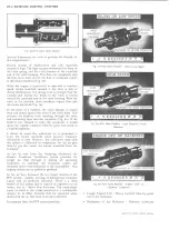
Fig. lc —Exhaust Gas Reciculation System Schematic
To tap this continuous supply of inert gases, without
external pipes or connection to the exhaust system,
additional exhaust gas passages are cast into the complex
runner system of the inlet manifold. Separating the two
EGR passages is a vacuum modulated shut-off and
metering valve, referred to as the “EGR valve” (fig. 2c).
The EGR valve contains a vacuum diaphragm, which is
operated by intake manifold vacuum. The diaphragm
vacuum signal supply port is located in the carburetor
throttle body, and is exposed to engine manifold vacuum
in the off-idle and part throttle to wide open throttle
operation. A .030 orifice in the valve vacuum tube serves
to modulate flow.
On In-Line engines the EGR valve is located on the inlet
manifold adjacent to the carburetor. Exhaust gases are
diverted from the manifold heat box through the EGR
valve and into the inlet manifold through a drilled hole
(fig. 3c).
Small V
8
engines have the EGR valve located externally
on the right rear side of the inlet manifold adjacent to
the rocker arm cover. Internally cast passages direct the
exhaust gases to the area just below the carburetor
throttle plates (fig. 4c).
VACUUM TUBE CONNECTED
V A L V E S E A T .
V A L V E C H A M B E R ..
T O IN T A K E
m a n i f o l d
\
J
___________m
Fig. 2c—EGR Valve-Sectional View
V A L V E O P E N
E X H A U S T G A S
IN L E T P O R T
LIGHT DUTY TRUCK SERVICE MANUAL
Summary of Contents for Light Duty Truck 1973
Page 1: ......
Page 4: ......
Page 6: ......
Page 53: ...HEATER AND AIR CONDITIONING 1A 27 LIGHT DUTY TRUCK SERVICE MANUAL...
Page 115: ...LIGHT DUTY TRUCK SERVICE M A N U A L HEATER AND AIR CONDITIONING 1A 89...
Page 123: ...BODY 1B 3 Fig 6 Typical 06 Van LIGHT DUTY TRUCK SERVICE MANUAL...
Page 149: ...BODY 1B 29 Fig 84 Body Mounting 06 Fig 85 Body Mounting 14 LIGHT DUTY TRUCK SERVICE MANUAL...
Page 171: ...LIGHT DUTY TRUCK SERVICE M A N U A L Fig 2 Frame Horizontal Checking Typical FRAME 2 3...
Page 173: ...LIGHT DUTY TRUCK SERVICE M A N U A L Fig 4 10 30 Series Truck Frame FRAME 2 5...
Page 174: ...2 6 FRAME LIGHT DUTY TRUCK SERVICE MANUAL Fig 5 Underbody Reference Points G Van...
Page 185: ...FRONT SUSPENSION 3 11 Fig 16 Toe out on Turns LIGHT DUTY TRUCK SERVICE MANUAL...
Page 224: ......
Page 266: ......
Page 351: ...ENGINE 6 15 Fig ID Sectional View of Eight Cylinder Engine LIGHT DUTY TRUCK SERVICE MANUAL...
Page 375: ...EN G IN E 6 39 LIGHT DUTY TRUCK SERVICE MANUAL...
Page 376: ...6 4 0 ENGINE LIGHT DUTY TRUCK SERVICE MANUAL...
Page 377: ...ENG IN E 6 41 LIGHT DUTY TRUCK SERVICE MANUAL...
Page 378: ...LIGHT DUTY TRUCK SERVICE MANUAL Fig 37L K Series Engine Front Mount 6 42 ENG INE...
Page 400: ...6 6 4 ENG INE LIGHT DUTY TRUCK SERVICE MANUAL...
Page 401: ...ENG IN E 6 65 LIGHT DUTY TRUCK SERVICE MANUAL...
Page 402: ...6 6 6 ENGINE LIGHT DUTY TRUCK SERVICE MANUAL...
Page 403: ...E NG IN E 6 67 Fig 36V C Series Engine Mounts LIGHT DUTY TRUCK SERVICE MANUAL...
Page 410: ......
Page 423: ...EN G IN E C OOLING 6K 13 Fig 16 Overheating Chart LIGHT DUTY TRUCK SERVICE MANUAL...
Page 424: ...6 K 1 4 ENG INE COOLING Fig 17 Coolant Loss Chart LIGHT DUTY TRUCK SERVICE MANUAL...
Page 456: ...6M 32 ENGINE FUEL Fig K15 Accelerator Controls G Van L 6 LIGHT DUTY TRUCK SERVICE MANUAL...
Page 492: ......
Page 512: ...Fig 18e Vacuum Advance Diagram V8 Engine...
Page 516: ...6 T 2 4 E M IS S IO N CONTROL SYSTEMS LIGHT DUTY TRUCK SERVICE MANUAL...
Page 528: ......
Page 590: ......
Page 593: ...CLUTCHES MANUAL TRANSMISSIONS 7M 3 LIGHT DUTY TRUCK SERVICE MANUAL...
Page 598: ...7M 8 CLUTCHES MANUAL TRANSMISSIONS LIGHT DUTY TRUCK SERVICE MANUAL...
Page 642: ......
Page 654: ......
Page 743: ...FUEL TANKS AND EXHAUST 8 13 LIGHT DUTY TRUCK SERVICE MANUAL...
Page 744: ...8 14 FUEL TANKS AND EXHAUST LIGHT DUTY TRUCK SERVICE MANUAL...
Page 760: ...8 30 FUEL TANKS AND EXHAUST Fig 40 Exhaust Pipe P Models LIGHT DUTY TRUCK SERVICE MANUAL...
Page 761: ...FUEL TANKS AND EXHAUST 8 31 LIGHT DUTY TRUCK SERVICE MANUAL...
Page 763: ...FUEL TANKS AND EXHAUST 8 33 LIGHT DUTY TRUCK SERVICE MANUAL...
Page 766: ......
Page 832: ...LIGHT DUTY TRUCK SERVICE MANUAL Fig 106 Power Steering Pump Mounting Typical 9 66 STEERING...
Page 833: ...PUMP ASSEMBLY STEERING GEAR TYPICAL SMALL V8 TYPICAL LARGE V8 STEERING 9 67...
Page 861: ...STEERING 9 95 Fig 134 Power Steering Pump Leakage LIGHT DUTY TRUCK SERVICE MANUAL...
Page 864: ......
Page 876: ......
Page 886: ...11 10 CHASSIS SHEET METAL LIGHT DUTY TRUCK SERVICE MANUAL...
Page 891: ...ELECTRICAL BODY AND CHASSIS 12 5 LIGHT DUTY TRUCK SERVICE MANUAL...
Page 934: ......
Page 942: ......
Page 970: ......
Page 972: ......
Page 974: ......
Page 976: ...V...
Page 978: ......
Page 979: ......


