BRAKES
5-5
is pushed forward. The fluid in the master cylinder, and
the entire system, being incompressible, transmits the
force exerted by the master cylinder piston to all the
inner surfaces of the system. At this point only the
pistons in the wheel cylinders or caliper are free to move,
and since the hydraulic fluid is not compressible, the
pistons move outward to force brake shoes against the
brake drums or disc.
To work properly a hydraulic brake system must be
leakproof, sturdy and filled with the right type of fluid.
The right type of fluid is one that has no corrosive effect
on the system’s parts, and does not readily freeze, boil or
vaporize at the temperature extremes encountered in
vehicle use.
PRESSURE AND FORCE (Fig. 5)
One of the advantages of a hydraulic system is that we
have the same pressure inside the system and up to all
wheels. This does not mean however that we are
applying the same force at each wheel; in fact, it permits
us to apply unequal force under certain circumstances.
NOTE: Pressure may be different at front or
rear wheels due to valving. Valves are
covered later in this section.
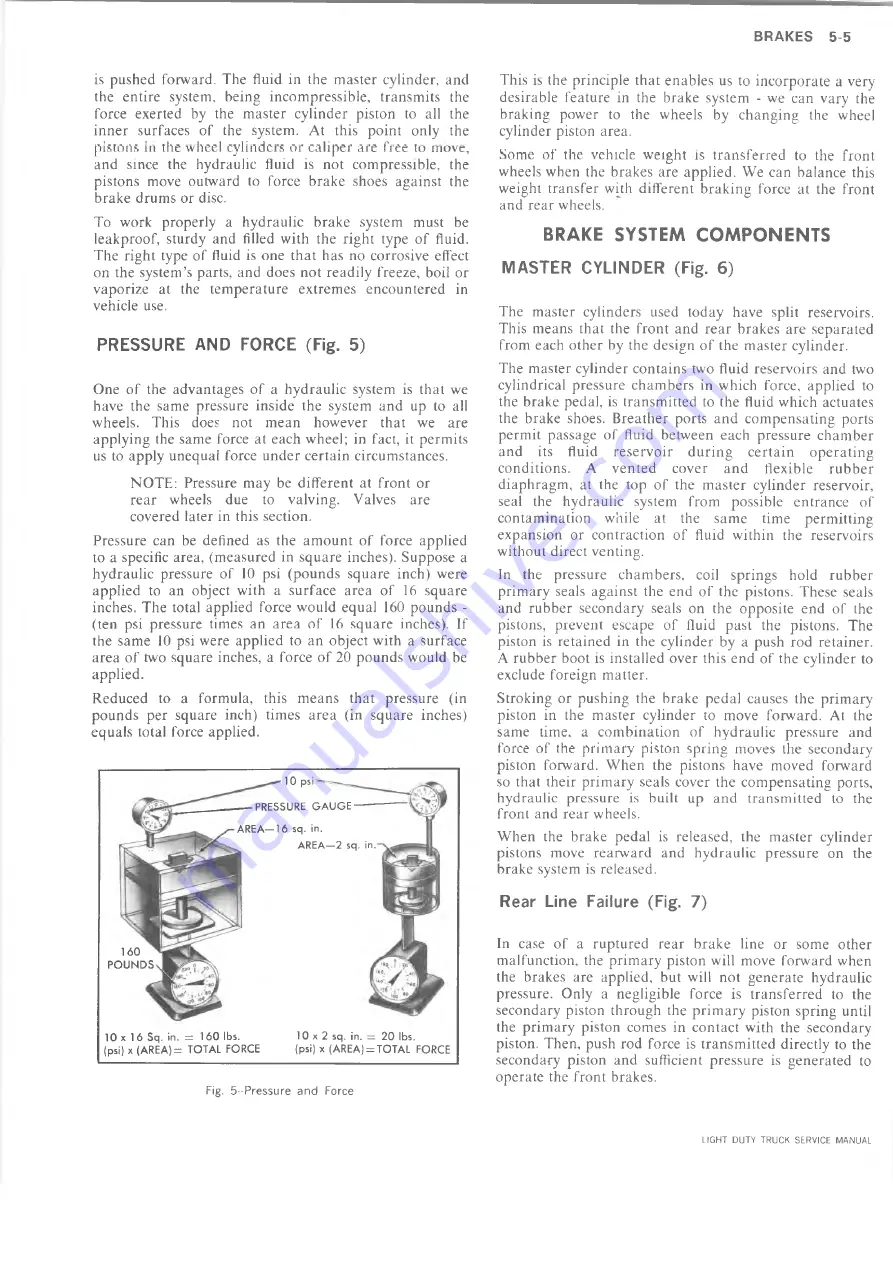
Pressure can be defined as the amount of force applied
to a specific area, (measured in square inches). Suppose a
hydraulic pressure of
10
psi (pounds square inch) were
applied to an object with a surface area of 16 square
inches. The total applied force would equal 160 pounds -
(ten psi pressure times an area of 16 square inches). If
the same
10
psi were applied to an object with a surface
area of two square inches, a force of
20
pounds would be
applied.
Reduced to a formula, this means that pressure (in
pounds per square inch) times area (in square inches)
equals total force applied.
Fig. 5 -Pressure and Force
This is the principle that enables us to incorporate a very
desirable feature in the brake system - we can vary the
braking power to the wheels by changing the wheel
cylinder piston area.
Some of the vehicle weight is transferred to the front
wheels when the brakes are applied. We can balance this
weight transfer with different braking force at the front
and rear wheels.
BRAKE SYSTEM COMPONENTS
MASTER CYLINDER (Fig. 6)
The master cylinders used today have split reservoirs.
This means that the front and rear brakes are separated
from each other by the design of the master cylinder.
The master cylinder contains two fluid reservoirs and two
cylindrical pressure chambers in which force, applied to
the brake pedal, is transmitted to the fluid which actuates
the brake shoes. Breather ports and compensating ports
permit passage of fluid between each pressure chamber
and its fluid reservoir during certain operating
conditions. A vented cover and flexible rubber
diaphragm, at the top of the master cylinder reservoir,
seal the hydraulic system from possible entrance of
contamination while at the same time permitting
expansion or contraction of fluid within the reservoirs
without direct venting.
In the pressure chambers, coil springs hold rubber
primary seals against the end of the pistons. These seals
and rubber secondary seals on the opposite end of the
pistons, prevent escape of fluid past the pistons. The
piston is retained in the cylinder by a push rod retainer.
A rubber boot is installed over this end of the cylinder to
exclude foreign matter.
Stroking or pushing the brake pedal causes the primary
piston in the master cylinder to move forward. At the
same time, a combination of hydraulic pressure and
force of the primary piston spring moves the secondary
piston forward. When the pistons have moved forward
so that their primary seals cover the compensating ports,
hydraulic pressure is built up and transmitted to the
front and rear wheels.
When the brake pedal is released, the master cylinder
pistons move rearward and hydraulic pressure on the
brake system is released.
Rear Line Failure (Fig. 7)
In case of a ruptured rear brake line or some other
malfunction, the primary piston will move forward when
the brakes are applied, but will not generate hydraulic
pressure. Only a negligible force is transferred to the
secondary piston through the primary piston spring until
the primary piston comes in contact with the secondary
piston. Then, push rod force is transmitted directly to the
secondary piston and sufficient pressure is generated to
operate the front brakes.
10 psi
PRESSURE GAUGE
AREA—16 sq. in.
AREA—2 sq. in.
160
POUNDS
10 x 1 6 Sq. in. = 160 lbs.
10 x 2 sq. in. = 20 lbs.
(psi) x (AREA)= TOTAL FORCE
(psi) x (AREA) = TOTAL FORCE
LIGHT DUTY TRUCK SERVICE MANUAL
Summary of Contents for Light Duty Truck 1973
Page 1: ......
Page 4: ......
Page 6: ......
Page 53: ...HEATER AND AIR CONDITIONING 1A 27 LIGHT DUTY TRUCK SERVICE MANUAL...
Page 115: ...LIGHT DUTY TRUCK SERVICE M A N U A L HEATER AND AIR CONDITIONING 1A 89...
Page 123: ...BODY 1B 3 Fig 6 Typical 06 Van LIGHT DUTY TRUCK SERVICE MANUAL...
Page 149: ...BODY 1B 29 Fig 84 Body Mounting 06 Fig 85 Body Mounting 14 LIGHT DUTY TRUCK SERVICE MANUAL...
Page 171: ...LIGHT DUTY TRUCK SERVICE M A N U A L Fig 2 Frame Horizontal Checking Typical FRAME 2 3...
Page 173: ...LIGHT DUTY TRUCK SERVICE M A N U A L Fig 4 10 30 Series Truck Frame FRAME 2 5...
Page 174: ...2 6 FRAME LIGHT DUTY TRUCK SERVICE MANUAL Fig 5 Underbody Reference Points G Van...
Page 185: ...FRONT SUSPENSION 3 11 Fig 16 Toe out on Turns LIGHT DUTY TRUCK SERVICE MANUAL...
Page 224: ......
Page 266: ......
Page 351: ...ENGINE 6 15 Fig ID Sectional View of Eight Cylinder Engine LIGHT DUTY TRUCK SERVICE MANUAL...
Page 375: ...EN G IN E 6 39 LIGHT DUTY TRUCK SERVICE MANUAL...
Page 376: ...6 4 0 ENGINE LIGHT DUTY TRUCK SERVICE MANUAL...
Page 377: ...ENG IN E 6 41 LIGHT DUTY TRUCK SERVICE MANUAL...
Page 378: ...LIGHT DUTY TRUCK SERVICE MANUAL Fig 37L K Series Engine Front Mount 6 42 ENG INE...
Page 400: ...6 6 4 ENG INE LIGHT DUTY TRUCK SERVICE MANUAL...
Page 401: ...ENG IN E 6 65 LIGHT DUTY TRUCK SERVICE MANUAL...
Page 402: ...6 6 6 ENGINE LIGHT DUTY TRUCK SERVICE MANUAL...
Page 403: ...E NG IN E 6 67 Fig 36V C Series Engine Mounts LIGHT DUTY TRUCK SERVICE MANUAL...
Page 410: ......
Page 423: ...EN G IN E C OOLING 6K 13 Fig 16 Overheating Chart LIGHT DUTY TRUCK SERVICE MANUAL...
Page 424: ...6 K 1 4 ENG INE COOLING Fig 17 Coolant Loss Chart LIGHT DUTY TRUCK SERVICE MANUAL...
Page 456: ...6M 32 ENGINE FUEL Fig K15 Accelerator Controls G Van L 6 LIGHT DUTY TRUCK SERVICE MANUAL...
Page 492: ......
Page 512: ...Fig 18e Vacuum Advance Diagram V8 Engine...
Page 516: ...6 T 2 4 E M IS S IO N CONTROL SYSTEMS LIGHT DUTY TRUCK SERVICE MANUAL...
Page 528: ......
Page 590: ......
Page 593: ...CLUTCHES MANUAL TRANSMISSIONS 7M 3 LIGHT DUTY TRUCK SERVICE MANUAL...
Page 598: ...7M 8 CLUTCHES MANUAL TRANSMISSIONS LIGHT DUTY TRUCK SERVICE MANUAL...
Page 642: ......
Page 654: ......
Page 743: ...FUEL TANKS AND EXHAUST 8 13 LIGHT DUTY TRUCK SERVICE MANUAL...
Page 744: ...8 14 FUEL TANKS AND EXHAUST LIGHT DUTY TRUCK SERVICE MANUAL...
Page 760: ...8 30 FUEL TANKS AND EXHAUST Fig 40 Exhaust Pipe P Models LIGHT DUTY TRUCK SERVICE MANUAL...
Page 761: ...FUEL TANKS AND EXHAUST 8 31 LIGHT DUTY TRUCK SERVICE MANUAL...
Page 763: ...FUEL TANKS AND EXHAUST 8 33 LIGHT DUTY TRUCK SERVICE MANUAL...
Page 766: ......
Page 832: ...LIGHT DUTY TRUCK SERVICE MANUAL Fig 106 Power Steering Pump Mounting Typical 9 66 STEERING...
Page 833: ...PUMP ASSEMBLY STEERING GEAR TYPICAL SMALL V8 TYPICAL LARGE V8 STEERING 9 67...
Page 861: ...STEERING 9 95 Fig 134 Power Steering Pump Leakage LIGHT DUTY TRUCK SERVICE MANUAL...
Page 864: ......
Page 876: ......
Page 886: ...11 10 CHASSIS SHEET METAL LIGHT DUTY TRUCK SERVICE MANUAL...
Page 891: ...ELECTRICAL BODY AND CHASSIS 12 5 LIGHT DUTY TRUCK SERVICE MANUAL...
Page 934: ......
Page 942: ......
Page 970: ......
Page 972: ......
Page 974: ......
Page 976: ...V...
Page 978: ......
Page 979: ......


