6 K - 4 E N G IN E C O O L IN G
WARM WATER
FROM ENGINE
COLD RADIATOR TRANSMISSION
FILL LEVEL
OIL COOLER
LINES
RADIATOR CODE'
LOCATION
COOLED WATER
TO ENGINE
Fig. 5—Typical Cross-Flow Radiator
held against its seat by a spring, which, when
compressed, allows excessive pressure to be relieved out
the radiator overflow. The vacuum valve is also held
against its seat by a spring which, when compressed,
opens the valve to relieve the vacuum created when the
system cools.
Fan
The cooling fan is located on the end of the water pump
shaft and is driven by the same belt that drives the
pump. In some instances a fan shroud surrounds the fan.
This shroud increases the cooling system efficiency by
ensuring that all air pulled in by the fan passes through
the radiator. Basically there are two types of fans: a fixed
drive fan (which rotates at water pump - engine rpm -
speed) and the automatic fan clutch.
Automatic fan clutches, Figure 6, are hydraulic devices
used to vary the speed in relation to the engine
temperature. Automatic fan clutches are used with many
engines, especially those equipped with factory installed
air conditioning units. Automatic fan clutches permit the
use of a high delivery fan to insure adequate cooling at
reduced engine speeds while eliminating overcooling,
excessive noise, and power loss at high speeds.
The automatic fan clutch has two modes of operation,
the engaged mode and the disengaged mode. The
disengaged mode (engine cold or high speed driving)
occurs when the silicone fluid is contained in the
reservoir area of the fan clutch. As the temperature of
the engine rises so does the temperature of the bimetallic
coil. This bimetallic coil is connected to the arm shaft in
such a way that as the temperature rises the shaft moves
the arm exposing an opening in the pump plate. This
opening allows the silicone fluid to flow from the
reservoir into the working chamber of the automatic fan
clutch.
The silicone fluid is kept circulating through the fan
clutch by wipers located on the pump plate. A hole is
located in front of each wiper, Figure 7. The speed
differential between the clutch plate and the pump plate
develops high pressure areas in front of the wipers, thus
the fluid is forced back into the reservoir. But as the
temperature rises the arm uncovers more of the large
opening and allows more of the silicone fluid to re-enter
the working chamber.
The automatic fan clutch becomes fully engaged when
the silicone fluid, circulating between the working
chamber and the reservoir, reaches a sufficient level in
the working chamber to completely fill the grooves in the
clutch body and clutch plate.
The resistance of the silicone fluid to the shearing action
caused by the speed differential between the grooves
transmits torque to the clutch body. The reverse situation
occurs when the temperature drops. The arm slowly
closes off the return hole thus blocking the fluid flow
from the reservoir into the working chamber.
The continuous action of the wipers removes the silicone
fluid from the grooves in the working chamber and
reduces the shearing action. Thus, less torque is
transmitted to the clutch body and the speed of the fan
decreases.
The temperature at which the automatic fan clutch
engages and disengages is controlled by the setting of
the bimetallic coil. This setting is tailored to satisfy the
cooling requirements of each model.
FAN CLUTCH DIAGNOSTIC
PROCEDURE
1.
NOISE
Fan noise is sometimes evident under the following
normal conditions: a. when clutch is engaged for
maximum cooling, and b. during first few minutes after
start-up until the clutch can re-distribute the silicone
fluid back to its normal disengaged operating condition
after overnight settling.
However, fan noise or an excessive roar will generally
occur continuously under all high engine speed
conditions (2500 r.p.m. and up) if the clutch assembly is
locked up due to an internal failure. If the fan cannot be
roated by hand or there is a rough grating feel as the
fan is turned, the clutch should be replaced.
2.
LOOSENESS
Under various temperature conditions, there is a visible
lateral movement that can be observed at the tip of the
fan blade. This is a normal condition due to the type of
bearing used. Approximately 1/4" maximum lateral
movement measured at the fan tip is allowable. This is
not cause for replacement.
3.
SILICONE FLUID LEAK
The operation of the unit is generally not affected by
small fluid leaks which may occur in the area around the
bearing assembly. However, if the degree of leakage
appears excessive, proceed to item 4.
LIGHT DUTY TRUCK SERVICE MANUAL
Summary of Contents for Light Duty Truck 1973
Page 1: ......
Page 4: ......
Page 6: ......
Page 53: ...HEATER AND AIR CONDITIONING 1A 27 LIGHT DUTY TRUCK SERVICE MANUAL...
Page 115: ...LIGHT DUTY TRUCK SERVICE M A N U A L HEATER AND AIR CONDITIONING 1A 89...
Page 123: ...BODY 1B 3 Fig 6 Typical 06 Van LIGHT DUTY TRUCK SERVICE MANUAL...
Page 149: ...BODY 1B 29 Fig 84 Body Mounting 06 Fig 85 Body Mounting 14 LIGHT DUTY TRUCK SERVICE MANUAL...
Page 171: ...LIGHT DUTY TRUCK SERVICE M A N U A L Fig 2 Frame Horizontal Checking Typical FRAME 2 3...
Page 173: ...LIGHT DUTY TRUCK SERVICE M A N U A L Fig 4 10 30 Series Truck Frame FRAME 2 5...
Page 174: ...2 6 FRAME LIGHT DUTY TRUCK SERVICE MANUAL Fig 5 Underbody Reference Points G Van...
Page 185: ...FRONT SUSPENSION 3 11 Fig 16 Toe out on Turns LIGHT DUTY TRUCK SERVICE MANUAL...
Page 224: ......
Page 266: ......
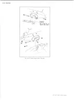
Page 351: ...ENGINE 6 15 Fig ID Sectional View of Eight Cylinder Engine LIGHT DUTY TRUCK SERVICE MANUAL...
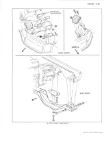
Page 375: ...EN G IN E 6 39 LIGHT DUTY TRUCK SERVICE MANUAL...
Page 376: ...6 4 0 ENGINE LIGHT DUTY TRUCK SERVICE MANUAL...
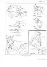
Page 377: ...ENG IN E 6 41 LIGHT DUTY TRUCK SERVICE MANUAL...
Page 378: ...LIGHT DUTY TRUCK SERVICE MANUAL Fig 37L K Series Engine Front Mount 6 42 ENG INE...
Page 400: ...6 6 4 ENG INE LIGHT DUTY TRUCK SERVICE MANUAL...
Page 401: ...ENG IN E 6 65 LIGHT DUTY TRUCK SERVICE MANUAL...
Page 402: ...6 6 6 ENGINE LIGHT DUTY TRUCK SERVICE MANUAL...
Page 403: ...E NG IN E 6 67 Fig 36V C Series Engine Mounts LIGHT DUTY TRUCK SERVICE MANUAL...
Page 410: ......
Page 423: ...EN G IN E C OOLING 6K 13 Fig 16 Overheating Chart LIGHT DUTY TRUCK SERVICE MANUAL...
Page 424: ...6 K 1 4 ENG INE COOLING Fig 17 Coolant Loss Chart LIGHT DUTY TRUCK SERVICE MANUAL...
Page 456: ...6M 32 ENGINE FUEL Fig K15 Accelerator Controls G Van L 6 LIGHT DUTY TRUCK SERVICE MANUAL...
Page 492: ......
Page 512: ...Fig 18e Vacuum Advance Diagram V8 Engine...
Page 516: ...6 T 2 4 E M IS S IO N CONTROL SYSTEMS LIGHT DUTY TRUCK SERVICE MANUAL...
Page 528: ......
Page 590: ......
Page 593: ...CLUTCHES MANUAL TRANSMISSIONS 7M 3 LIGHT DUTY TRUCK SERVICE MANUAL...
Page 598: ...7M 8 CLUTCHES MANUAL TRANSMISSIONS LIGHT DUTY TRUCK SERVICE MANUAL...
Page 642: ......
Page 654: ......
Page 743: ...FUEL TANKS AND EXHAUST 8 13 LIGHT DUTY TRUCK SERVICE MANUAL...
Page 744: ...8 14 FUEL TANKS AND EXHAUST LIGHT DUTY TRUCK SERVICE MANUAL...
Page 760: ...8 30 FUEL TANKS AND EXHAUST Fig 40 Exhaust Pipe P Models LIGHT DUTY TRUCK SERVICE MANUAL...
Page 761: ...FUEL TANKS AND EXHAUST 8 31 LIGHT DUTY TRUCK SERVICE MANUAL...
Page 763: ...FUEL TANKS AND EXHAUST 8 33 LIGHT DUTY TRUCK SERVICE MANUAL...
Page 766: ......
Page 832: ...LIGHT DUTY TRUCK SERVICE MANUAL Fig 106 Power Steering Pump Mounting Typical 9 66 STEERING...
Page 833: ...PUMP ASSEMBLY STEERING GEAR TYPICAL SMALL V8 TYPICAL LARGE V8 STEERING 9 67...
Page 861: ...STEERING 9 95 Fig 134 Power Steering Pump Leakage LIGHT DUTY TRUCK SERVICE MANUAL...
Page 864: ......
Page 876: ......
Page 886: ...11 10 CHASSIS SHEET METAL LIGHT DUTY TRUCK SERVICE MANUAL...
Page 891: ...ELECTRICAL BODY AND CHASSIS 12 5 LIGHT DUTY TRUCK SERVICE MANUAL...
Page 934: ......
Page 942: ......
Page 970: ......
Page 972: ......
Page 974: ......
Page 976: ...V...
Page 978: ......
Page 979: ......


