HEATER A N D AIR C O N D IT I O N I N G
1A-29
1
2
3
4
5
6
7
8
9
10
11
12
13
14
15
16
17
18
19
2 0
21 22
2 3
24
2 5
2 6
2 7
2 8
2 9
3 0
31
32
3 3
3 4 35 3 6 37
38 3 9
4 0
1.
Rear Head
15.
Pulley and Bearing Assembly
28.
Thrust Bearing
2.
Rear Head to Shell " O " Ring
16.
Pulley Bearing
29.
Thrust Race
3.
Rear Discharge Valve Plate
17.
Pulley Bearing Retainer Ring
30.
Compressor Shell
4.
Rear Suction Reed Plate
18.
Pulley and Bearing Retainer Ring
31.
C ylinder Assembly
5.
Piston Ring
19.
Clutch Hub and Drive Plate Assembly
32.
Shaft Seal
6.
Piston Drive Ball
20.
Super Heat Sw itch, " O ” Ring and
33.
Shaft Seal Seat ” 0 " Ring
7.
Ball Seat
Retainer Ring (G Models O nly)
34.
Shaft Seal Seat
8.
Piston
21.
High Pressure Relief Valve
35.
Shaft Seal Seat Retainer Ring
9.
Front Suction Reed Plate
22.
Oil Pump Gears
36.
Absorbent Sleeve
10.
Front Discharge Valve Plate
23.
Mainshaft Bearing (Rear)
37.
Absorbent Sleeve Retainer
11.
F ront Head to Shell " O ” Ring
24.
Oil In le t Tube " 0 " Ring
38.
Spacer
12.
F ront Head
25.
Oil Inlet Tube
39.
Clutch Hub Retainer Ring
13.
Coil and Housing Assembly
26.
Wobble Plate and Mainshaft Assembly
40.
Shaft Nut
14.
Coil Housing Retainer Ring
27.
T hrust Race
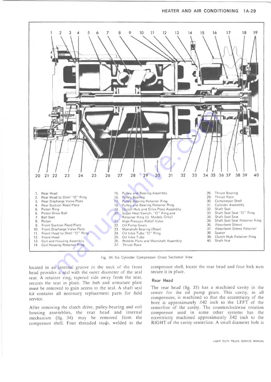
Fig. 34 -Six Cylinder Compressor- Cross Sectional View
located in an internal groove in the neck of the front
head provides a seal with the outer diameter of the seal
seat. A retainer ring, tapered side away from the seat,
secures the seat in place. The hub and armature plate
must be removed to gain access to the seal. A shaft seal
kit contains all necessary replacement parts for field
service.
After removing the clutch drive, pulley-bearing and coil
housing assemblies, the rear head and internal
mechanism (fig. 34) may be removed from the
compressor shell. Four threaded stu4s, welded to the
compressor shell, locate the rear head and four lock nuts
secure it in place.
Rear Head
The rear head (fig. 35) has a machined cavity in the
center for the oil pump gears. This cavity, in all
compressors, is machined so that the eccentricity of the
bore is approximately .042 inch to the LEFT of the
centerline of the cavity. The counterclockwise rotation
compressor used in some other systems has the
eccentricity machined approximately .042 inch to the
RIGHT of the cavity centerline. A small diameter hole is
LIGHT DUTY TRUCK SERVICE MANUAL
Summary of Contents for Light Duty Truck 1973
Page 1: ......
Page 4: ......
Page 6: ......
Page 53: ...HEATER AND AIR CONDITIONING 1A 27 LIGHT DUTY TRUCK SERVICE MANUAL...
Page 115: ...LIGHT DUTY TRUCK SERVICE M A N U A L HEATER AND AIR CONDITIONING 1A 89...
Page 123: ...BODY 1B 3 Fig 6 Typical 06 Van LIGHT DUTY TRUCK SERVICE MANUAL...
Page 149: ...BODY 1B 29 Fig 84 Body Mounting 06 Fig 85 Body Mounting 14 LIGHT DUTY TRUCK SERVICE MANUAL...
Page 171: ...LIGHT DUTY TRUCK SERVICE M A N U A L Fig 2 Frame Horizontal Checking Typical FRAME 2 3...
Page 173: ...LIGHT DUTY TRUCK SERVICE M A N U A L Fig 4 10 30 Series Truck Frame FRAME 2 5...
Page 174: ...2 6 FRAME LIGHT DUTY TRUCK SERVICE MANUAL Fig 5 Underbody Reference Points G Van...
Page 185: ...FRONT SUSPENSION 3 11 Fig 16 Toe out on Turns LIGHT DUTY TRUCK SERVICE MANUAL...
Page 224: ......
Page 266: ......
Page 351: ...ENGINE 6 15 Fig ID Sectional View of Eight Cylinder Engine LIGHT DUTY TRUCK SERVICE MANUAL...
Page 375: ...EN G IN E 6 39 LIGHT DUTY TRUCK SERVICE MANUAL...
Page 376: ...6 4 0 ENGINE LIGHT DUTY TRUCK SERVICE MANUAL...
Page 377: ...ENG IN E 6 41 LIGHT DUTY TRUCK SERVICE MANUAL...
Page 378: ...LIGHT DUTY TRUCK SERVICE MANUAL Fig 37L K Series Engine Front Mount 6 42 ENG INE...
Page 400: ...6 6 4 ENG INE LIGHT DUTY TRUCK SERVICE MANUAL...
Page 401: ...ENG IN E 6 65 LIGHT DUTY TRUCK SERVICE MANUAL...
Page 402: ...6 6 6 ENGINE LIGHT DUTY TRUCK SERVICE MANUAL...
Page 403: ...E NG IN E 6 67 Fig 36V C Series Engine Mounts LIGHT DUTY TRUCK SERVICE MANUAL...
Page 410: ......
Page 423: ...EN G IN E C OOLING 6K 13 Fig 16 Overheating Chart LIGHT DUTY TRUCK SERVICE MANUAL...
Page 424: ...6 K 1 4 ENG INE COOLING Fig 17 Coolant Loss Chart LIGHT DUTY TRUCK SERVICE MANUAL...
Page 456: ...6M 32 ENGINE FUEL Fig K15 Accelerator Controls G Van L 6 LIGHT DUTY TRUCK SERVICE MANUAL...
Page 492: ......
Page 512: ...Fig 18e Vacuum Advance Diagram V8 Engine...
Page 516: ...6 T 2 4 E M IS S IO N CONTROL SYSTEMS LIGHT DUTY TRUCK SERVICE MANUAL...
Page 528: ......
Page 590: ......
Page 593: ...CLUTCHES MANUAL TRANSMISSIONS 7M 3 LIGHT DUTY TRUCK SERVICE MANUAL...
Page 598: ...7M 8 CLUTCHES MANUAL TRANSMISSIONS LIGHT DUTY TRUCK SERVICE MANUAL...
Page 642: ......
Page 654: ......
Page 743: ...FUEL TANKS AND EXHAUST 8 13 LIGHT DUTY TRUCK SERVICE MANUAL...
Page 744: ...8 14 FUEL TANKS AND EXHAUST LIGHT DUTY TRUCK SERVICE MANUAL...
Page 760: ...8 30 FUEL TANKS AND EXHAUST Fig 40 Exhaust Pipe P Models LIGHT DUTY TRUCK SERVICE MANUAL...
Page 761: ...FUEL TANKS AND EXHAUST 8 31 LIGHT DUTY TRUCK SERVICE MANUAL...
Page 763: ...FUEL TANKS AND EXHAUST 8 33 LIGHT DUTY TRUCK SERVICE MANUAL...
Page 766: ......
Page 832: ...LIGHT DUTY TRUCK SERVICE MANUAL Fig 106 Power Steering Pump Mounting Typical 9 66 STEERING...
Page 833: ...PUMP ASSEMBLY STEERING GEAR TYPICAL SMALL V8 TYPICAL LARGE V8 STEERING 9 67...
Page 861: ...STEERING 9 95 Fig 134 Power Steering Pump Leakage LIGHT DUTY TRUCK SERVICE MANUAL...
Page 864: ......
Page 876: ......
Page 886: ...11 10 CHASSIS SHEET METAL LIGHT DUTY TRUCK SERVICE MANUAL...
Page 891: ...ELECTRICAL BODY AND CHASSIS 12 5 LIGHT DUTY TRUCK SERVICE MANUAL...
Page 934: ......
Page 942: ......
Page 970: ......
Page 972: ......
Page 974: ......
Page 976: ...V...
Page 978: ......
Page 979: ......


