HEATER A N D AIR C O N D IT IO N IN G
1A-19
Receiver-Dehydrator.......................................................1A-76
Sight G lass........................................................................1A-76
Blower-Evaporator Assembly...................................... .1A-76
Blower Assembly............................................................ .1A-77
Expansion Valve, Evaporator Case or Core..........1A-77
Thermostatic and/or Blower Switches.....................1A-78
Resistor...............................................................................1A-78
Fuse.....................................................................................1A-78
Diagnosis..............................................................................1A-78
Refrigerant System.........................................................1A-78
Compressor Diagnosis....................................................1A-80
Insufficient Cooling........................................................ 1A-81
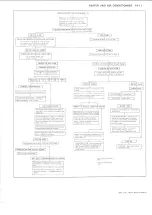
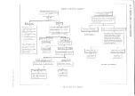
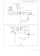
Electrical System Diagnosis........................................ .1A-83
Vacuum System Diagnosis.......................................... .1A-87
Special Tools.......................................................................1A-94
GENERAL DESCRIPTION
FOUR-SEASON SYSTEM (C-K MODELS)
Both the heating and cooling functions are performed by
this system. Air enterning the vehicle must pass through
the cooling unit (evaporator) and through (or around)
the heating unit, in that order, and the system is thus
referred to as a "reheat" system.
The evaporator provides maximum cooling of the air
passing through the core when the air conditioning
system is calling for cooling. A thermostatic switch,
located in the blower-evaporator case, acts to control
compressor operation by sensing the fin temperature of
the evaporator core.
System operation is as follows: Air, either outside air or
recirculated air, enters the system and is forced through
the system by the blower. As the air passes through the
evaporator core, it receives maximum cooling if the air
conditioning controls are calling for cooling. After
leaving the evaporator, the air enters the Heater and Air
Conditioner Selector Duct Assembly where, by means of
diverter doors, it is caused to pass through or to bypass
the heater core in the proportions necessary to provide
the desired outlet temperature. Conditioned air then
enters the vehicle through either the floor distributor
duct or the dash outlets. When, during cooling
operations, the air is cooled by the evaporator to below
comfort level, it is then warmed by the heater to the
desired temperature. During "heating only" operations,
the evaporator will not be in operation and ambient air
will be warmed to the desired level in the same manner.
The dash outlets are rectangular in design. The outlets
can be rotated horizontally or vertically to direct air as
desired. Under the left distributor duct is located a floor
cooler which can be rotated to provide cooling air or shut
off completely.
FLOOR MOUNTED SYSTEM (G MODELS)
This system (C62) performs the cooling functions only.
When heating (above ambient temperatures) is desired,
the standard equipment heater must be used. When air
conditioning is desired, be sure the heater is completely
shut off.
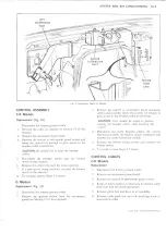
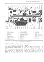
This self contained unit (fig. 22), operates on recirculated
inside air only. Recirculated air is drawn into the unit,
passes through the evaporator core (receiving maximum
cooling) and then directed into the vehicle through
adjustable outlets located in the ducts.
A thermostatic switch, located on the evaporator cover, is
used to control compressor operation by sensing air
temperature as it leaves the evaporator core.
OVERHEAD SYSTEMS (C-K-G MODELS)
These systems (C69 on C-K Models, C63 on G Models)
operate in conjunction with the Four-Season System (C-
K Models) or Floor Mounted System (G Models)-they
do not operate independently.
NOTE: Overhead system kits are available
for non-factory installation on C-K Models,
providing the vehicle is equipped with the
front system.
Like the floor-mounted system, these units are self
contained, operating on inside (recirculated) air only. Air
is drawn into the unit, passed through the evaporator
core and then directed into the passenger compartment
through adjustable outlets in the air distributor duct.
System control is through the thermostatic switch in the
front system. The only control on the overhead system is
a three speed blower switch.
MOTOR HOME CHASSIS SYSTEM
This system performs the cooling functions only. When
Fig. 22--C62 Interior Components (G Models)
LIGHT DUTY TRUCK SERVICE MANUAL
Summary of Contents for Light Duty Truck 1973
Page 1: ......
Page 4: ......
Page 6: ......
Page 53: ...HEATER AND AIR CONDITIONING 1A 27 LIGHT DUTY TRUCK SERVICE MANUAL...
Page 115: ...LIGHT DUTY TRUCK SERVICE M A N U A L HEATER AND AIR CONDITIONING 1A 89...
Page 123: ...BODY 1B 3 Fig 6 Typical 06 Van LIGHT DUTY TRUCK SERVICE MANUAL...
Page 149: ...BODY 1B 29 Fig 84 Body Mounting 06 Fig 85 Body Mounting 14 LIGHT DUTY TRUCK SERVICE MANUAL...
Page 171: ...LIGHT DUTY TRUCK SERVICE M A N U A L Fig 2 Frame Horizontal Checking Typical FRAME 2 3...
Page 173: ...LIGHT DUTY TRUCK SERVICE M A N U A L Fig 4 10 30 Series Truck Frame FRAME 2 5...
Page 174: ...2 6 FRAME LIGHT DUTY TRUCK SERVICE MANUAL Fig 5 Underbody Reference Points G Van...
Page 185: ...FRONT SUSPENSION 3 11 Fig 16 Toe out on Turns LIGHT DUTY TRUCK SERVICE MANUAL...
Page 224: ......
Page 266: ......
Page 351: ...ENGINE 6 15 Fig ID Sectional View of Eight Cylinder Engine LIGHT DUTY TRUCK SERVICE MANUAL...
Page 375: ...EN G IN E 6 39 LIGHT DUTY TRUCK SERVICE MANUAL...
Page 376: ...6 4 0 ENGINE LIGHT DUTY TRUCK SERVICE MANUAL...
Page 377: ...ENG IN E 6 41 LIGHT DUTY TRUCK SERVICE MANUAL...
Page 378: ...LIGHT DUTY TRUCK SERVICE MANUAL Fig 37L K Series Engine Front Mount 6 42 ENG INE...
Page 400: ...6 6 4 ENG INE LIGHT DUTY TRUCK SERVICE MANUAL...
Page 401: ...ENG IN E 6 65 LIGHT DUTY TRUCK SERVICE MANUAL...
Page 402: ...6 6 6 ENGINE LIGHT DUTY TRUCK SERVICE MANUAL...
Page 403: ...E NG IN E 6 67 Fig 36V C Series Engine Mounts LIGHT DUTY TRUCK SERVICE MANUAL...
Page 410: ......
Page 423: ...EN G IN E C OOLING 6K 13 Fig 16 Overheating Chart LIGHT DUTY TRUCK SERVICE MANUAL...
Page 424: ...6 K 1 4 ENG INE COOLING Fig 17 Coolant Loss Chart LIGHT DUTY TRUCK SERVICE MANUAL...
Page 456: ...6M 32 ENGINE FUEL Fig K15 Accelerator Controls G Van L 6 LIGHT DUTY TRUCK SERVICE MANUAL...
Page 492: ......
Page 512: ...Fig 18e Vacuum Advance Diagram V8 Engine...
Page 516: ...6 T 2 4 E M IS S IO N CONTROL SYSTEMS LIGHT DUTY TRUCK SERVICE MANUAL...
Page 528: ......
Page 590: ......
Page 593: ...CLUTCHES MANUAL TRANSMISSIONS 7M 3 LIGHT DUTY TRUCK SERVICE MANUAL...
Page 598: ...7M 8 CLUTCHES MANUAL TRANSMISSIONS LIGHT DUTY TRUCK SERVICE MANUAL...
Page 642: ......
Page 654: ......
Page 743: ...FUEL TANKS AND EXHAUST 8 13 LIGHT DUTY TRUCK SERVICE MANUAL...
Page 744: ...8 14 FUEL TANKS AND EXHAUST LIGHT DUTY TRUCK SERVICE MANUAL...
Page 760: ...8 30 FUEL TANKS AND EXHAUST Fig 40 Exhaust Pipe P Models LIGHT DUTY TRUCK SERVICE MANUAL...
Page 761: ...FUEL TANKS AND EXHAUST 8 31 LIGHT DUTY TRUCK SERVICE MANUAL...
Page 763: ...FUEL TANKS AND EXHAUST 8 33 LIGHT DUTY TRUCK SERVICE MANUAL...
Page 766: ......
Page 832: ...LIGHT DUTY TRUCK SERVICE MANUAL Fig 106 Power Steering Pump Mounting Typical 9 66 STEERING...
Page 833: ...PUMP ASSEMBLY STEERING GEAR TYPICAL SMALL V8 TYPICAL LARGE V8 STEERING 9 67...
Page 861: ...STEERING 9 95 Fig 134 Power Steering Pump Leakage LIGHT DUTY TRUCK SERVICE MANUAL...
Page 864: ......
Page 876: ......
Page 886: ...11 10 CHASSIS SHEET METAL LIGHT DUTY TRUCK SERVICE MANUAL...
Page 891: ...ELECTRICAL BODY AND CHASSIS 12 5 LIGHT DUTY TRUCK SERVICE MANUAL...
Page 934: ......
Page 942: ......
Page 970: ......
Page 972: ......
Page 974: ......
Page 976: ...V...
Page 978: ......
Page 979: ......


