E M I S S I O N C O N T R O L S Y S T E M S
6 T -9
6
. Connect vacuum line to tube at top of valve.
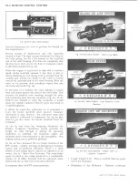
EGR Valve Functional Check
NOTE: A rough idling engine may be caused
by a malfunction of the EGR valve; such as,
exhaust deposits holding valve open, broken
EGR valve spring, vacuum hose disconnected
or a ruptured valve diaphragm.
On Vehicle Check
1. Connect tachometer to engine.
2. With engine running at normal operating tempera
ture and choke valve is fully open position, set
engine speed at 2000 rpm - transmission in Park or
neutral, parking brake on and drive wheels blocked.
3. Disconnect vacuum hose at EGR valve and check to
make sure that vacuum is available at valve -
reconnect hose.
4. Observe tachometer to make sure that engine speed
is at 2000 rpm. Disconnect vacuum hose at EGR
valve and observe tachometer reading. Valve is
functioning properly if a minimum increase of
100
rpm is noted with vacuum hose disconnected.
Off Vehicle Check
1. Manually depress the EGR valve diaphragm to
make sure valve is free - if diaphragm cannot be
moved manually valve should be cleaned before
proceeding with check.
2. Apply approximately 9 inches of vacuum to the
vacuum tube on top of EGR valve. The valve
should move to the fully open position, and should
remain open - no leak down - with vacuum applied.
3. Replace valve if diaphragm is defective.
EGR Valve Cleaning
CAUTION:
Do not wash valve assembly in
solvents or degreaser-permanent damage to
valve diaphragm may result.
1. Clean base of valve with a wire brush or wheel to
remove exhaust deposits from mounting surface.
2. Valve seat and pintle should be cleaned in a
standard abrasive-type spark plug cleaning
machine.
3. Insert valve and pintle into opening in cleaning
machine, and blast for approximately 30 seconds.
4. Compress diaphragm spring so that valve is fully
unseated, repeat cleaning for approximately 30
seconds.
5. Inspect valve to ensure that exhaust deposits have
been removed - repeat cleaning procedure as
required to remove all deposits.
6
. Air blast valve seat and pintle area to ensure that
abrasive material is thoroughly removed from
valve.
TRANSMISSION CONTROLLED SPARK SYSTEM
SIX-CYLINDER ENGINE
The Transmission Controlled Spark System is used on all
10 Series vehicles, C-K20 Suburban, G20 Series and G30
passenger vans.
DESCRIPTION
Control of exhaust emitted by vehicles using the six-
cylinder engine, is accomplished by preventing ignition
vacuum advance when the vehicle is operating in low
forward gears.
Vacuum advance is controlled by a solenoid-operated
valve, which is energized by grounding a normally open
switch at the transmission. When the solenoid is in the
non-energized position, vacuum to the distributor
advance unit is shut off and the distributor is vented to
atmosphere through a filter at the opposite end of the
solenoid — venting the distributor advance unit prevents
it from becoming locked at an advanced position. When
the solenoid is energized, the vacuum port is uncovered
and the plunger is seated at the opposite end, shutting off
the clean air vent. High gear deceleration throttle blade
setting is performed with the solenoid de-energized.
The CEC solenoid is controlled by two switches and a
time relay. The solenoid is energized in the high forward
gear and in reverse on Hydra-matic by a transmission
operated switch. A thermostatic coolant temperature
switch is used to provide thermal override below 93°F.
The time relay is incorporated in the circuit to energize
the CEC valve for approximately 20 seconds after the
ignition key is turned on. The relay’s 20 second delay
begins when the ignition key is turned on, but the
solenoid will remain energized as long as coolant
temperature is below 93°F.
Wider throttle blade openings at idle are required to
compensate for the retarded spark condition produced
by the design of the emission reduction system. To
prevent engine dieseling at engine shut down, an idle
stop solenoid is provided. The ignition activated idle stop
solenoid eliminates dieseling tendencies by allowing the
throttle valve to close beyond the normal idle position
when the ignition is turned off.
SYSTEM THEORY
The TCS system components are shown in their normal
at rest position with the engine off and cold (fig. Id). The
temperature switch points are closed, making contact
with the cold terminal; the time relay points are closed,
LIGHT DUTY TRUCK SERVICE MANUAL
Summary of Contents for Light Duty Truck 1973
Page 1: ......
Page 4: ......
Page 6: ......
Page 53: ...HEATER AND AIR CONDITIONING 1A 27 LIGHT DUTY TRUCK SERVICE MANUAL...
Page 115: ...LIGHT DUTY TRUCK SERVICE M A N U A L HEATER AND AIR CONDITIONING 1A 89...
Page 123: ...BODY 1B 3 Fig 6 Typical 06 Van LIGHT DUTY TRUCK SERVICE MANUAL...
Page 149: ...BODY 1B 29 Fig 84 Body Mounting 06 Fig 85 Body Mounting 14 LIGHT DUTY TRUCK SERVICE MANUAL...
Page 171: ...LIGHT DUTY TRUCK SERVICE M A N U A L Fig 2 Frame Horizontal Checking Typical FRAME 2 3...
Page 173: ...LIGHT DUTY TRUCK SERVICE M A N U A L Fig 4 10 30 Series Truck Frame FRAME 2 5...
Page 174: ...2 6 FRAME LIGHT DUTY TRUCK SERVICE MANUAL Fig 5 Underbody Reference Points G Van...
Page 185: ...FRONT SUSPENSION 3 11 Fig 16 Toe out on Turns LIGHT DUTY TRUCK SERVICE MANUAL...
Page 224: ......
Page 266: ......
Page 351: ...ENGINE 6 15 Fig ID Sectional View of Eight Cylinder Engine LIGHT DUTY TRUCK SERVICE MANUAL...
Page 375: ...EN G IN E 6 39 LIGHT DUTY TRUCK SERVICE MANUAL...
Page 376: ...6 4 0 ENGINE LIGHT DUTY TRUCK SERVICE MANUAL...
Page 377: ...ENG IN E 6 41 LIGHT DUTY TRUCK SERVICE MANUAL...
Page 378: ...LIGHT DUTY TRUCK SERVICE MANUAL Fig 37L K Series Engine Front Mount 6 42 ENG INE...
Page 400: ...6 6 4 ENG INE LIGHT DUTY TRUCK SERVICE MANUAL...
Page 401: ...ENG IN E 6 65 LIGHT DUTY TRUCK SERVICE MANUAL...
Page 402: ...6 6 6 ENGINE LIGHT DUTY TRUCK SERVICE MANUAL...
Page 403: ...E NG IN E 6 67 Fig 36V C Series Engine Mounts LIGHT DUTY TRUCK SERVICE MANUAL...
Page 410: ......
Page 423: ...EN G IN E C OOLING 6K 13 Fig 16 Overheating Chart LIGHT DUTY TRUCK SERVICE MANUAL...
Page 424: ...6 K 1 4 ENG INE COOLING Fig 17 Coolant Loss Chart LIGHT DUTY TRUCK SERVICE MANUAL...
Page 456: ...6M 32 ENGINE FUEL Fig K15 Accelerator Controls G Van L 6 LIGHT DUTY TRUCK SERVICE MANUAL...
Page 492: ......
Page 512: ...Fig 18e Vacuum Advance Diagram V8 Engine...
Page 516: ...6 T 2 4 E M IS S IO N CONTROL SYSTEMS LIGHT DUTY TRUCK SERVICE MANUAL...
Page 528: ......
Page 590: ......
Page 593: ...CLUTCHES MANUAL TRANSMISSIONS 7M 3 LIGHT DUTY TRUCK SERVICE MANUAL...
Page 598: ...7M 8 CLUTCHES MANUAL TRANSMISSIONS LIGHT DUTY TRUCK SERVICE MANUAL...
Page 642: ......
Page 654: ......
Page 743: ...FUEL TANKS AND EXHAUST 8 13 LIGHT DUTY TRUCK SERVICE MANUAL...
Page 744: ...8 14 FUEL TANKS AND EXHAUST LIGHT DUTY TRUCK SERVICE MANUAL...
Page 760: ...8 30 FUEL TANKS AND EXHAUST Fig 40 Exhaust Pipe P Models LIGHT DUTY TRUCK SERVICE MANUAL...
Page 761: ...FUEL TANKS AND EXHAUST 8 31 LIGHT DUTY TRUCK SERVICE MANUAL...
Page 763: ...FUEL TANKS AND EXHAUST 8 33 LIGHT DUTY TRUCK SERVICE MANUAL...
Page 766: ......
Page 832: ...LIGHT DUTY TRUCK SERVICE MANUAL Fig 106 Power Steering Pump Mounting Typical 9 66 STEERING...
Page 833: ...PUMP ASSEMBLY STEERING GEAR TYPICAL SMALL V8 TYPICAL LARGE V8 STEERING 9 67...
Page 861: ...STEERING 9 95 Fig 134 Power Steering Pump Leakage LIGHT DUTY TRUCK SERVICE MANUAL...
Page 864: ......
Page 876: ......
Page 886: ...11 10 CHASSIS SHEET METAL LIGHT DUTY TRUCK SERVICE MANUAL...
Page 891: ...ELECTRICAL BODY AND CHASSIS 12 5 LIGHT DUTY TRUCK SERVICE MANUAL...
Page 934: ......
Page 942: ......
Page 970: ......
Page 972: ......
Page 974: ......
Page 976: ...V...
Page 978: ......
Page 979: ......


