


with
each
service
kit.
Install
seal
following
procedures outlined on the supplied instruction
sheet.
2.
Set the valve spring and d a m p e r and valve cap
in place.
3.
Com press the spring with Tool
J-5892
and
install the valve locks then release the compressor tool,
m ak in g sure the locks seat properly in the groove o f the
valve stem.
N O T E : G rease may be used to hold the locks in
place while releasing the compressor tool.
4.
Install spark plug an d torque to specifications.
5.
Install and adjust valve m echanism as previously
outlined.
VALVE LIFTERS
H ydraulic valve lifters very seldom require a tte n
tion. The
lifters are extremely simple in design,
readjustm ents are not necessary, and servicing o f the
lifters requires only th at care and cleanliness be
exercised in the handling o f parts.
Locating Noisy Lifters
Locate a noisy valve lifter by using a piece o f
g a rd e n hose approxim ately four feet in length. Place one
end o f the hose n ear the end o f each intake and exhaust
valve with the other end o f the hose to the ear. In this
m an n er, the sound is localized making it easy to
determ in e which lifter is at fault.
A n o th e r m ethod is to place a finger on the face o f
the valve spring retainer. If the lifter is not functioning
properly, a distinct shock will be felt w hen the valve
returns to its seat.
T h e general types o f valve lifter noise are as
follows:
1.
Hard R ap p in g N o is e - U s u a lly caused by the
plunger becom ing tight in the bore o f the lifter body to
such an extent that the retu rn spring can no longer push
the plunger back up to w orking position. Probable causes
are:
a.
Excessive varnish or carbon deposit causing
a b n o rm a l stickiness.
b.
G allin g or "p ic k -u p " between plu nger and
bore o f lifter body, usually caused by an abrasive piece
o f dirt or metal w edging between plunger and lifter
body.
2.
M oderate R a p p in g N oise-Probable causes are:
a.
Excessively high leakdown rate.
b.
Leaky check valve seat.
c.
Im p ro p er adjustm ent.
3.
G e n e ra l Noise T h ro u g h o u t the Valve T rain-This
will, in most cases, be caused by either insufficient oil
supply or im p ro p e r adjustm ent.
4.
Interm ittent Clicking-Probable causes are:
a.
A microscopic piece o f dirt m om entarily
caught between ball seat an d check valve ball.
b.
In rare cases, the ball itself m ay be out-of-
ro und o r have a flat spot.
c.
Im p ro p e r adjustment.
In most cases where noise exists in one or more
lifters all lifter units should be removed, disassembled,
cleaned in a solvent, reassembled, and reinstalled in the
engine. If dirt, corrosion, carbon, etc. is shown to exist in
one unit, it more likely exists in all the units, thus it
would only be a m atter o f time before all lifters caused
trouble.
Removal
1.
Remove intake m anifold as previously outlined.
2.
R em ove
valve
m ec h a n ism
as
previously
outlined.
3.
Remove valve lifters.
NOTE: Place valve lifters in a rack so that they
m ay be reinstalled in the same location.
Installation
1.
Install valve lifters.
NOTE: W henever new valve lifters are being
installed, coat foot o f valve lifters with "M o ly k o te"
or its equivalent.
2.
Install intake m anifold as previously outlined.
3.
Install and adjust valve m echanism as outlined.
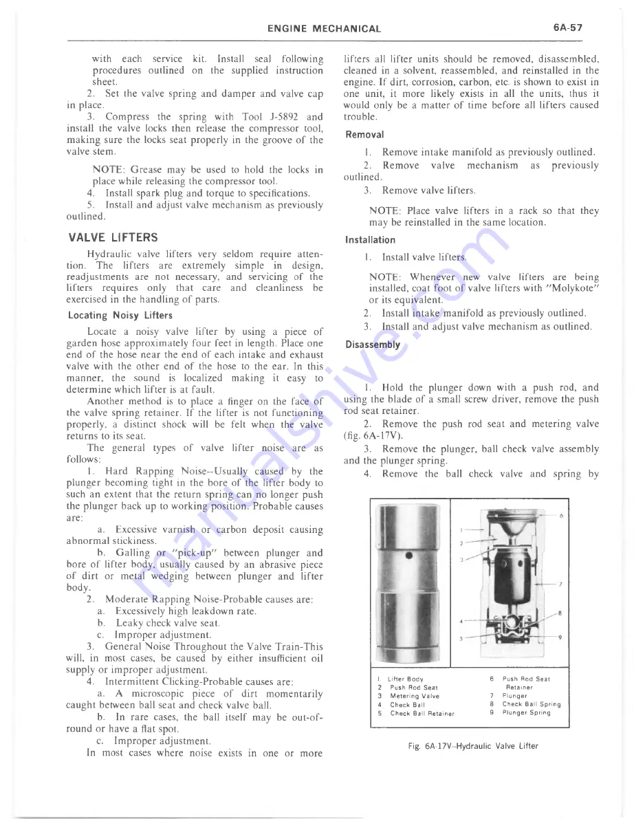
Disassembly
1.
Hold the plunger down with a push rod, and
using the blade o f a small screw driver, remove the push
rod seat retainer.
2.
Remove the push rod seat and m etering valve
(fig. 6A-17V).
3.
Remove the plunger, ball check valve assembly
and the plunger spring.
4.
Remove the ball check valve and spring by
I. L ifte r B o d y
2 Push Rod S e a t
3. M e te rin g V a lv e
4
C h e c k B a ll
5
C h e c k B a ll R e ta in e r
6
Push Rod S e at
R e ta in e r
7
P lu n g e r
8
C h e c k B a ll S p rin g
9
P lu n g e r S p rin g
Summary of Contents for 1977 light duty truck
Page 1: ......
Page 28: ......
Page 70: ...Fig IB 24 Four Season System Vacuum Diagram C K Models 1B 24 LIGHT TRUCK SERVICE M A N U A L...
Page 71: ...Fig lB 25 Overhead System Wiring Diagram C K Models AIR C O N D ITIO N IN G 1 B 2 5...
Page 72: ...Fig IB 26 C60 System Wiring Diagram G Models...
Page 74: ......
Page 75: ...Fig lB 29 Motor Home Chassis Wiring Diagram THERMOSTATIC SWITCH AIR C O N D ITIO N IN G IB 2 9...
Page 106: ......
Page 128: ......
Page 129: ...Fig 2D 5 Typical 05 and 0 6 Vans...
Page 136: ......
Page 148: ...Fig 2D 51 Rear Door Controls...
Page 158: ...Fig 2D 79 Folding Top Assembly...
Page 159: ...Fig 2D 80 Folding Top Side Moldings and Header...
Page 161: ...Fig 2D 85 Dnver s Bucket Seat 14 Fig 2D 86 Passenger s Bucket Seat 14...
Page 162: ...Fig 2D 89 Rear Folding Seat 06 Fig 2D 9 0 Rear Bench Seat 14...
Page 163: ......
Page 164: ......
Page 165: ......
Page 185: ......
Page 186: ......
Page 190: ......
Page 225: ......
Page 226: ......
Page 248: ...Fig 3B 77 Removing Bearing Housing Pivot Pins Fig 3B 79 Replacing Lock Bolt Spring...
Page 278: ...C 10 G 10 20 C 20 30 G 30 P 10 30 9 Fig 3C l Front Suspension C P Series...
Page 284: ...BALL JOINT DIAGNOSTIC PROCEDURE...
Page 316: ......
Page 321: ...Fig 3D 12 Rear Spring Installation G Models...
Page 322: ......
Page 325: ......
Page 326: ......
Page 336: ......
Page 352: ......
Page 378: ......
Page 395: ...Fig 5 2 Front Brake Pipes and Hoses C K Models...
Page 396: ......
Page 397: ...Fig 5 4 Front Brake Pipes and Hoses P Models BRAKES 5 1 3...
Page 400: ......
Page 401: ...V 8 N 4 0 L 6 N 4 0...
Page 402: ......
Page 404: ......
Page 405: ...P300 42 M40 JB9...
Page 438: ......
Page 448: ...Fig 6A 4 P Series Engine Rear Mount...
Page 451: ...Fig 6A 8 K Series Engine Rear Mount...
Page 452: ...ENGINE M O U N T BRACKET ALL K SERIES W ITH L 6 ENGINE 6A14 LIGHT TRUCK SERVICE M A N U A L...
Page 483: ...FUEL PUMP PUSH ROD OILING OIL F LTER AND BY PASS VALVE...
Page 484: ...FUEL PUMP PUSH ROD OILING CRANKCASE AND CRANKSHAFT OILING VALVE MECHANISM OILING...
Page 487: ......
Page 488: ...MOUNT VIEW A V AUTOMATIC TRANSMISSION FRONT MANUAL TRANSMISSION...
Page 489: ......
Page 490: ......
Page 568: ......
Page 602: ......
Page 605: ......
Page 612: ...Fig 6D 3i High Energy Ignition Basic W iring...
Page 644: ......
Page 648: ...DISTRIBUTOR VALVE Fig 6E 3 Vacuum Hose Schematic L6 292 CID Calif HD Emissions...
Page 649: ...V A LV E Fig 6E 5 Vacuum Hose Schematic V8 305 CID HD Emissions...
Page 650: ...Fig 6E 7 Vacuum Hose Schematic V8 350 CID High Altitude Calif LD Emissions...
Page 651: ...VALVE Fig 6E 9 Vacuum Hose Schematic V8 350 400 CID Except Calif HD Emissions...
Page 652: ...CANISTER...
Page 653: ...PCV V AL VE Fig 6E 13 Vacuum Hose Schematic V8 454 CID Except Calif HD Emissions...
Page 672: ...Fig 6E 29 Air Cleaner 305 350 400 V8 CK...
Page 682: ......
Page 692: ......
Page 700: ...Fig 7A 6B Detent Downshift Cable C K and P Series...
Page 709: ...Fig 7 A 12B CBC 350 Hydraulic Circuit A U TO M A T IC T R A N S M IS S IO N 7 A 1 7...
Page 743: ...VIEW B FLAT IvEwfDl l6 G tO 2 GAGE...
Page 744: ......
Page 755: ...V I E W B WITH AUTOMATIC TRANSMISSION WITH MANUAL TRANSMISSION V I E W A...
Page 760: ...r...
Page 766: ......
Page 767: ...V I E W D 1 6 ENGINE VIEW V 8 ENGINE...
Page 768: ......
Page 775: ......
Page 788: ......
Page 794: ...G A S G A U G E...
Page 805: ......
Page 836: ...Fig 8 58 Seat Belt Reminder System Schematic...
Page 844: ...C H E C K n...
Page 852: ......
Page 853: ...SPECIAL TOOLS J 2 3 5 2 0...


