


p re lo a d " is obtained (See specifications section). W hen
the p ro p e r preload has been obtained, tighten the
adjuster plug locknut to specifications and recheck
torque. If the gear feels " lu m p y " after adjustment, there
is pro b ab ly d a m a g e in the bearings due to severe im pact
or im p ro p e r adjustm ent; the g ear must be disassembled
and inspected for rep lacem en t o f d a m a g e d parts.
9.
Adjust "over-center p re lo a d " as follows:
a.
T urn the steering wheel gently from one stop
all the way to the other carefully counting the total
n u m b e r o f turns. T urn the wheel back exactly half-way,
to center position.
b.
T urn the lash adjuster screw clockwise to take
out all lash between the ball nut an d p itm an shaft sector
teeth and then tighten the locknut.
c.
Check the torque at the steering wheel, taking
the highest re a d in g as the wheel is turned through center
position. See the Specifications Section for p ro p er over
center preload.
d.
If necessary, loosen locknut and readjust lash
adjuster screw to obtain p ro p e r torque. T ighten the
locknut to specifications and again check torque reading
through center o f travel.
N O T E : If m a x im u m specification is exceeded, turn
lash adjuster screw counterclockwise, then come up
on adjustm ent by turn in g the adjuster in a
clockwise motion.
10.
Reassem ble the p itm a n arm to the p itm an
shaft, lining up the m arks m ade during disassembly.
T o rq u e the p itm a n shaft nut to sspecifications.
CAUTION:
I f a clamp type p itm an arm is used,
spread the p itm an arm ju s t enough, with a
wedge, to slip the arm onto the p itm a n shaft.
Do not spread the clam p more than required to
slip over pitm a n sh a ft with hand pressure. Do
not ham m er the p itm a n arm onto the pitm an
shaft. Be sure to install the hardened steel
washer before installing the nut.
11.
Install the horn button cap or shroud and
connect the battery g round cable.
12
Lower the vehicle to the floor.
S teerin g G ear High P oint C entering
1.
Set front wheels in straight ahead position. This
can be checked by driving vehicle a short distance on a
flat surface to determ in e steering wheel position at which
vehicle follows a straight path.
2.
W ith fro n t wheels set straight ahead, check
position o f m ark on w o rm sh a ft designating steering gear
high point. This mark should be at the top side o f the
sh a ft at 12 o ’clock position and lined up with the mark
in the coupling lower clamp.
3.
O n C, G and P series if g ear has been moved off
high point w hen setting wheel in straight ahead position.
Loosen adjusting sleeve clam ps on both left and right
h a n d tie rods, then turn both sleeves an equal n u m b e r o f
turns in the same direction to b rin g g ear back on high
point.
turns or in different directions will disturb the toe-
in setting o f the wheels.
4.
On K series if the gear has been moved off high
point when setting wheels in straight ahead position.
Loosen adjusting sleeve clamps on the connecting rod
then turn sleeve to bring gear back on high point.
5.
Readjust toe-in as outlined in Section 3A (if
necessary).
6.
Be sure to properly orient sleeves an d clamps as
shown in figures 3B-104, 3B-106 and 3B-109 when
fastening and torqueing clamps to p ro p er specifications.
Steering W heel A lignm ent
NOTE: On all series vehicles check steering gear
for high point centering before checking steering
wheel alignment.
1.
Set wheels in straight ah e a d position by driving
vehicle a short distance.
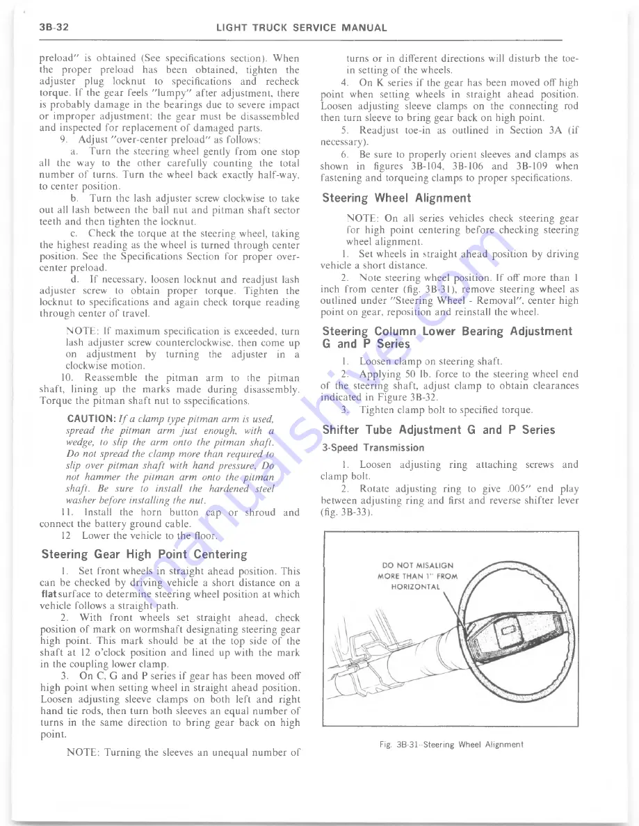
2.
N ote steering wheel position. If off more than 1
inch from center (fig. 3B-31), remove steering wheel as
outlined u n d e r "S teering Wheel - R em oval", center high
point on gear, reposition and reinstall the wheel.
Steering Colum n Lower Bearing A djustm ent
G and P Series
1.
Loosen clam p on steering shaft.
2. Applying 50 lb. force to the steering wheel end
o f the steering shaft, adjust clamp to o b ta in clearances
indicated in Figure 3B-32.
3.
Tighten clam p bolt to specified torque.
S hifter Tube Adjustm ent G and P Series
3-Speed T ransm ission
1.
Loosen adjusting ring attaching screws and
clam p bolt.
2.
Rotate adjusting ring to give .005" end play
between adjusting ring and first and reverse shifter lever
(fig. 3B-33).
N O T E : T u rn in g the sleeves an unequal n u m b e r o f
Summary of Contents for 1977 light duty truck
Page 1: ......
Page 28: ......
Page 70: ...Fig IB 24 Four Season System Vacuum Diagram C K Models 1B 24 LIGHT TRUCK SERVICE M A N U A L...
Page 71: ...Fig lB 25 Overhead System Wiring Diagram C K Models AIR C O N D ITIO N IN G 1 B 2 5...
Page 72: ...Fig IB 26 C60 System Wiring Diagram G Models...
Page 74: ......
Page 75: ...Fig lB 29 Motor Home Chassis Wiring Diagram THERMOSTATIC SWITCH AIR C O N D ITIO N IN G IB 2 9...
Page 106: ......
Page 128: ......
Page 129: ...Fig 2D 5 Typical 05 and 0 6 Vans...
Page 136: ......
Page 148: ...Fig 2D 51 Rear Door Controls...
Page 158: ...Fig 2D 79 Folding Top Assembly...
Page 159: ...Fig 2D 80 Folding Top Side Moldings and Header...
Page 161: ...Fig 2D 85 Dnver s Bucket Seat 14 Fig 2D 86 Passenger s Bucket Seat 14...
Page 162: ...Fig 2D 89 Rear Folding Seat 06 Fig 2D 9 0 Rear Bench Seat 14...
Page 163: ......
Page 164: ......
Page 165: ......
Page 185: ......
Page 186: ......
Page 190: ......
Page 225: ......
Page 226: ......
Page 248: ...Fig 3B 77 Removing Bearing Housing Pivot Pins Fig 3B 79 Replacing Lock Bolt Spring...
Page 278: ...C 10 G 10 20 C 20 30 G 30 P 10 30 9 Fig 3C l Front Suspension C P Series...
Page 284: ...BALL JOINT DIAGNOSTIC PROCEDURE...
Page 316: ......
Page 321: ...Fig 3D 12 Rear Spring Installation G Models...
Page 322: ......
Page 325: ......
Page 326: ......
Page 336: ......
Page 352: ......
Page 378: ......
Page 395: ...Fig 5 2 Front Brake Pipes and Hoses C K Models...
Page 396: ......
Page 397: ...Fig 5 4 Front Brake Pipes and Hoses P Models BRAKES 5 1 3...
Page 400: ......
Page 401: ...V 8 N 4 0 L 6 N 4 0...
Page 402: ......
Page 404: ......
Page 405: ...P300 42 M40 JB9...
Page 438: ......
Page 448: ...Fig 6A 4 P Series Engine Rear Mount...
Page 451: ...Fig 6A 8 K Series Engine Rear Mount...
Page 452: ...ENGINE M O U N T BRACKET ALL K SERIES W ITH L 6 ENGINE 6A14 LIGHT TRUCK SERVICE M A N U A L...
Page 483: ...FUEL PUMP PUSH ROD OILING OIL F LTER AND BY PASS VALVE...
Page 484: ...FUEL PUMP PUSH ROD OILING CRANKCASE AND CRANKSHAFT OILING VALVE MECHANISM OILING...
Page 487: ......
Page 488: ...MOUNT VIEW A V AUTOMATIC TRANSMISSION FRONT MANUAL TRANSMISSION...
Page 489: ......
Page 490: ......
Page 568: ......
Page 602: ......
Page 605: ......
Page 612: ...Fig 6D 3i High Energy Ignition Basic W iring...
Page 644: ......
Page 648: ...DISTRIBUTOR VALVE Fig 6E 3 Vacuum Hose Schematic L6 292 CID Calif HD Emissions...
Page 649: ...V A LV E Fig 6E 5 Vacuum Hose Schematic V8 305 CID HD Emissions...
Page 650: ...Fig 6E 7 Vacuum Hose Schematic V8 350 CID High Altitude Calif LD Emissions...
Page 651: ...VALVE Fig 6E 9 Vacuum Hose Schematic V8 350 400 CID Except Calif HD Emissions...
Page 652: ...CANISTER...
Page 653: ...PCV V AL VE Fig 6E 13 Vacuum Hose Schematic V8 454 CID Except Calif HD Emissions...
Page 672: ...Fig 6E 29 Air Cleaner 305 350 400 V8 CK...
Page 682: ......
Page 692: ......
Page 700: ...Fig 7A 6B Detent Downshift Cable C K and P Series...
Page 709: ...Fig 7 A 12B CBC 350 Hydraulic Circuit A U TO M A T IC T R A N S M IS S IO N 7 A 1 7...
Page 743: ...VIEW B FLAT IvEwfDl l6 G tO 2 GAGE...
Page 744: ......
Page 755: ...V I E W B WITH AUTOMATIC TRANSMISSION WITH MANUAL TRANSMISSION V I E W A...
Page 760: ...r...
Page 766: ......
Page 767: ...V I E W D 1 6 ENGINE VIEW V 8 ENGINE...
Page 768: ......
Page 775: ......
Page 788: ......
Page 794: ...G A S G A U G E...
Page 805: ......
Page 836: ...Fig 8 58 Seat Belt Reminder System Schematic...
Page 844: ...C H E C K n...
Page 852: ......
Page 853: ...SPECIAL TOOLS J 2 3 5 2 0...


