


th at noise is caused by rear axle assembly. The rear axle
should be tested on a smooth level road to avoid road
noise. It is not advisable to test rear axle for noise by
r u n n in g with re a r wheels jacked up.
Noises in rear axle assembly may be caused by a
faulty propeller shaft, faulty rear wheel bearings, faulty
differential or pinion shaft bearings, misalignm ent
between two U-joints, or w orn differential side gears and
pinions; noises may also be caused by mismatched,
im p ro p erly adjusted, or scored ring and pinion gear set.
Rear Wheel Bearing Noise-
A rough re a r wheel
b e a rin g produces a v ibration or growl which continues
with vehicle coasting and transm ission in neutral. A
brinelled re a r wheel bearing causes a knock or click
app ro x im ately every two revolutions o f re a r wheel, since
the bearing rollers do not travel at the same speed as the
re a r axle and wheel. With re a r wheels jacked up, spin
re a r wheels by hand while listening at hubs for evidence
o f rough or brinelled wheel bearing.
Differential Side Gear and Pinion
Noise^Differen-
tial side gears and pinions seldom cause noise since their
m o v em en t is relatively slight on straight ahead driving.
Noise produced by these gears will be most pronounced
on turns.
Pinion
Bearing
failu res can be distin g u ish ed
because they rotate at h ig h er speeds than differential
side bearings and axle sh aft bearings. Rough or
brinelled pinion bearings produce a continuous low
pitched w h irrin g or scraping noise starting at relatively
low speed.
Side Bearings
produce a constant rough noise o f a
lower pitch th a n pinion bearings. Side bearing noise m ay
also fluctuate in the above wheel bearing test.
N O T E : Bearing D iagnosis Charts a p p e a r later in
this section.
Gear Noise
T h e re are two basic types o f gear noise. The first
type is produced by broken, bent, or forcibly d a m a g e d
gear teeth an d is usually quite audible over the entire
speed range an d presents no particular problem in
diagnosis.
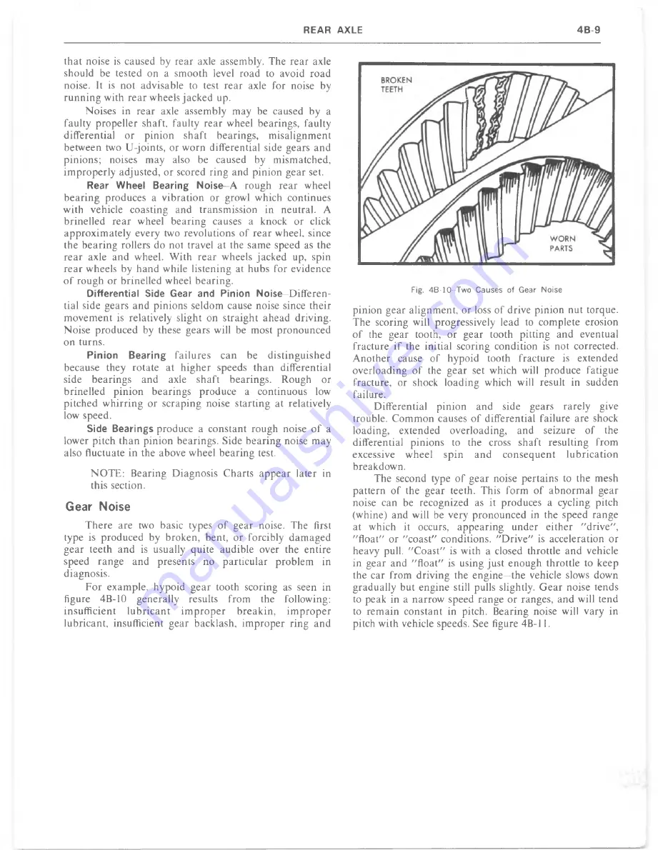
F o r example, hypoid g ear tooth scoring as seen in
figure 4B-10 generally results from the following:
insufficient
lu b ric a n t i m p r o p e r
break in ,
i m p r o p e r
lubricant, insufficient gear backlash, im p ro p er ring and
Fig. 4B-10--Two Causes of Gear Noise
pinion gear alignment, or loss o f drive pinion nut torque.
The scoring will progressively lead to complete erosion
o f the gear tooth, o r g ear tooth pitting and eventual
fracture if the initial scoring condition is not corrected.
A nother cause o f hypoid tooth fracture is extended
overloading o f the gear set which will produce fatigue
fracture, or shock lo ading which will result in sudden
failure.
Differential pinion an d side gears rarely give
trouble. C o m m o n causes o f differential failure are shock
loading, extended overloading, and seizure o f the
differential pinions to the cross shaft resulting from
excessive wheel
spin
an d
co n se q u e n t
lu b ricatio n
breakdown.
The second type o f gear noise pertains to the mesh
pattern o f the gear teeth. This form o f a b n o rm a l gear
noise can be recognized as it produces a cycling pitch
(whine) and will be very pronounced in the speed range
at which it occurs, a p p e a rin g under either "drive",
" float" or "c o a st" conditions. " D r iv e " is acceleration or
heavy pull. " C o a s t" is with a closed throttle an d vehicle
in gear and " flo a t" is using just enough throttle to keep
the car from driving the en g in e—the vehicle slows down
gradually but engine still pulls slightly. G e a r noise tends
to peak in a narrow speed range or ranges, and will tend
to rem ain constant in pitch. Bearing noise will vary in
pitch with vehicle speeds. See figure 4B-11.
Summary of Contents for 1977 light duty truck
Page 1: ......
Page 28: ......
Page 70: ...Fig IB 24 Four Season System Vacuum Diagram C K Models 1B 24 LIGHT TRUCK SERVICE M A N U A L...
Page 71: ...Fig lB 25 Overhead System Wiring Diagram C K Models AIR C O N D ITIO N IN G 1 B 2 5...
Page 72: ...Fig IB 26 C60 System Wiring Diagram G Models...
Page 74: ......
Page 75: ...Fig lB 29 Motor Home Chassis Wiring Diagram THERMOSTATIC SWITCH AIR C O N D ITIO N IN G IB 2 9...
Page 106: ......
Page 128: ......
Page 129: ...Fig 2D 5 Typical 05 and 0 6 Vans...
Page 136: ......
Page 148: ...Fig 2D 51 Rear Door Controls...
Page 158: ...Fig 2D 79 Folding Top Assembly...
Page 159: ...Fig 2D 80 Folding Top Side Moldings and Header...
Page 161: ...Fig 2D 85 Dnver s Bucket Seat 14 Fig 2D 86 Passenger s Bucket Seat 14...
Page 162: ...Fig 2D 89 Rear Folding Seat 06 Fig 2D 9 0 Rear Bench Seat 14...
Page 163: ......
Page 164: ......
Page 165: ......
Page 185: ......
Page 186: ......
Page 190: ......
Page 225: ......
Page 226: ......
Page 248: ...Fig 3B 77 Removing Bearing Housing Pivot Pins Fig 3B 79 Replacing Lock Bolt Spring...
Page 278: ...C 10 G 10 20 C 20 30 G 30 P 10 30 9 Fig 3C l Front Suspension C P Series...
Page 284: ...BALL JOINT DIAGNOSTIC PROCEDURE...
Page 316: ......
Page 321: ...Fig 3D 12 Rear Spring Installation G Models...
Page 322: ......
Page 325: ......
Page 326: ......
Page 336: ......
Page 352: ......
Page 378: ......
Page 395: ...Fig 5 2 Front Brake Pipes and Hoses C K Models...
Page 396: ......
Page 397: ...Fig 5 4 Front Brake Pipes and Hoses P Models BRAKES 5 1 3...
Page 400: ......
Page 401: ...V 8 N 4 0 L 6 N 4 0...
Page 402: ......
Page 404: ......
Page 405: ...P300 42 M40 JB9...
Page 438: ......
Page 448: ...Fig 6A 4 P Series Engine Rear Mount...
Page 451: ...Fig 6A 8 K Series Engine Rear Mount...
Page 452: ...ENGINE M O U N T BRACKET ALL K SERIES W ITH L 6 ENGINE 6A14 LIGHT TRUCK SERVICE M A N U A L...
Page 483: ...FUEL PUMP PUSH ROD OILING OIL F LTER AND BY PASS VALVE...
Page 484: ...FUEL PUMP PUSH ROD OILING CRANKCASE AND CRANKSHAFT OILING VALVE MECHANISM OILING...
Page 487: ......
Page 488: ...MOUNT VIEW A V AUTOMATIC TRANSMISSION FRONT MANUAL TRANSMISSION...
Page 489: ......
Page 490: ......
Page 568: ......
Page 602: ......
Page 605: ......
Page 612: ...Fig 6D 3i High Energy Ignition Basic W iring...
Page 644: ......
Page 648: ...DISTRIBUTOR VALVE Fig 6E 3 Vacuum Hose Schematic L6 292 CID Calif HD Emissions...
Page 649: ...V A LV E Fig 6E 5 Vacuum Hose Schematic V8 305 CID HD Emissions...
Page 650: ...Fig 6E 7 Vacuum Hose Schematic V8 350 CID High Altitude Calif LD Emissions...
Page 651: ...VALVE Fig 6E 9 Vacuum Hose Schematic V8 350 400 CID Except Calif HD Emissions...
Page 652: ...CANISTER...
Page 653: ...PCV V AL VE Fig 6E 13 Vacuum Hose Schematic V8 454 CID Except Calif HD Emissions...
Page 672: ...Fig 6E 29 Air Cleaner 305 350 400 V8 CK...
Page 682: ......
Page 692: ......
Page 700: ...Fig 7A 6B Detent Downshift Cable C K and P Series...
Page 709: ...Fig 7 A 12B CBC 350 Hydraulic Circuit A U TO M A T IC T R A N S M IS S IO N 7 A 1 7...
Page 743: ...VIEW B FLAT IvEwfDl l6 G tO 2 GAGE...
Page 744: ......
Page 755: ...V I E W B WITH AUTOMATIC TRANSMISSION WITH MANUAL TRANSMISSION V I E W A...
Page 760: ...r...
Page 766: ......
Page 767: ...V I E W D 1 6 ENGINE VIEW V 8 ENGINE...
Page 768: ......
Page 775: ......
Page 788: ......
Page 794: ...G A S G A U G E...
Page 805: ......
Page 836: ...Fig 8 58 Seat Belt Reminder System Schematic...
Page 844: ...C H E C K n...
Page 852: ......
Page 853: ...SPECIAL TOOLS J 2 3 5 2 0...


