


ON-VEHICLE SERVICE
8 - 1 / 2 and 8 - 7 / 8 RING
GEAR AXLE
AXLE ASSEMBLY
C onstruction o f the axle assembly is such that
service op eratio n s m ay be p e rfo rm e d with the housing
installed in the vehicle or with the housing installed in a
holding fixture. The following rem oval and installation
procedure is necessary only w hen the housing requires
replacem ent.
CAUTION:
See C A U T I O N on page 1 o f this
section, regarding A x le Assembly fasteners.
Removal
1.
Raise vehicle on hoist.
2.
Sup p o rt rear axle assembly with suitable lifting
device, so that tension is relieved in springs and shock
absorbers.
3.
Rem ove tru n n io n bearing
" U "
bolts from the
axle co m p an io n flange, separate tru n n io n from flange,
position propeller sh a ft to one side and tie it to fram e
side rail.
N O T E : Secure tru n n io n bearing caps to trunnion,
using m asking tape or a large ru b b e r band, to
p revent loss o f bearings.
4.
Disconnect shock absorbers at lower attachm ent
points and position out o f the way.
5.
Disconnect axle vent hose from vent connector
a n d position vent hose to one side.
6.
Disconnect hydraulic brake hose at connector on
axle housing. Remove brake d rum , disconnect park in g
brake cable at actuating levers and at flange plate. R efer
to Section 5 for cable rem oval and brake details. Remove
axle " U " bolt nuts,
" U "
bolts, spacers an d clam p plates.
7.
Lower axle assembly and remove from vehicle.
Installation
1.
Position axle assembly und er vehicle and align
w ith springs.
2.
Install spacer, clam p plate and " U " bolts to axle
assembly, loosely install re ta in in g nuts to " U " bolts.
3.
Position shock absorbers in lower attach m en t
brackets and loosely install nut to retain shock.
4.
C onnect axle vent hose to vent connector at
carrier.
5.
C onnect hydraulic brak e hose to connector on
axle housing, connect p ark in g brak e cable to actuating
levers. Install brake d rum and wheel and tire a s s e m b l y -
bleed brakes and adjust p ark in g brake as outlined in
applicable portion o f Section 5.
6.
Reassem ble the propeller shaft to com panion
flange, m ak in g sure that b earin g caps are indexed in
flange seat. T o rq u e b earin g cap retaining nuts to
specifications.
7.
Position vehicle so th at weight is placed on
suspension com ponents an d torque affected parts to
specifications.
8.
Lower vehicle and remove from hoist.
AXLE SHAFT
Removal
1.
Raise vehicle on hoist. Remove wheel and tire
assembly and brake drums.
2.
Clean all dirt from area o f carrier cover.
3.
D r a in lubricant fro m carrier by rem oving cover.
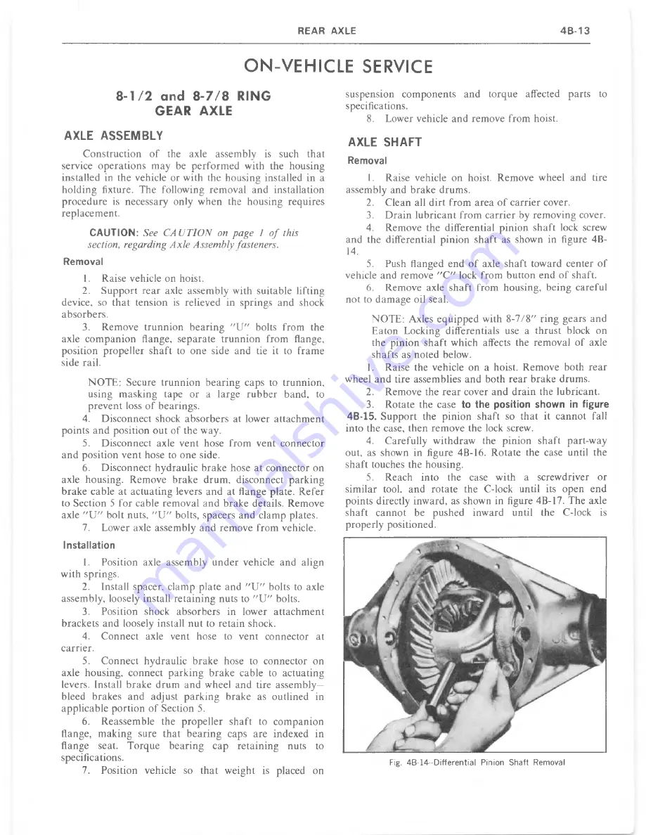
4.
Remove the differential pinion shaft lock screw
and the differential pinion shaft as shown in figure 4B-
14.
5.
Push flanged end o f axle shaft toward center o f
vehicle and remove
" C "
lock from button end o f shaft.
6.
Remove axle shaft from housing, being careful
not to d am ag e oil seal.
N O TE: Axles e quipped with 8 - 7 /8 " ring gears and
Eaton Locking differentials use a thrust block on
the pinion sh aft which affects the removal o f axle
shafts as noted below.
1.
Raise the vehicle on a hoist. Remove both rear
wheel an d tire assemblies and both re a r brake drums.
2.
Remove the re a r cover an d d ra in the lubricant.
3.
Rotate the case
to the position shown in figure
4B-15.
Support the pinion shaft so th at it can n o t fall
into the case, then remove the lock screw.
4.
Carefully w ithdraw the pinion shaft part-way
out, as shown in figure 4B-16. Rotate the case until the
shaft touches the housing.
5.
Reach into the case w ith a screwdriver or
sim ilar tool, and rotate the C-lock until its open end
points directly inward, as shown in figure 4B-17. The axle
shaft cannot be pushed inward until the C-lock is
properly positioned.
Summary of Contents for 1977 light duty truck
Page 1: ......
Page 28: ......
Page 70: ...Fig IB 24 Four Season System Vacuum Diagram C K Models 1B 24 LIGHT TRUCK SERVICE M A N U A L...
Page 71: ...Fig lB 25 Overhead System Wiring Diagram C K Models AIR C O N D ITIO N IN G 1 B 2 5...
Page 72: ...Fig IB 26 C60 System Wiring Diagram G Models...
Page 74: ......
Page 75: ...Fig lB 29 Motor Home Chassis Wiring Diagram THERMOSTATIC SWITCH AIR C O N D ITIO N IN G IB 2 9...
Page 106: ......
Page 128: ......
Page 129: ...Fig 2D 5 Typical 05 and 0 6 Vans...
Page 136: ......
Page 148: ...Fig 2D 51 Rear Door Controls...
Page 158: ...Fig 2D 79 Folding Top Assembly...
Page 159: ...Fig 2D 80 Folding Top Side Moldings and Header...
Page 161: ...Fig 2D 85 Dnver s Bucket Seat 14 Fig 2D 86 Passenger s Bucket Seat 14...
Page 162: ...Fig 2D 89 Rear Folding Seat 06 Fig 2D 9 0 Rear Bench Seat 14...
Page 163: ......
Page 164: ......
Page 165: ......
Page 185: ......
Page 186: ......
Page 190: ......
Page 225: ......
Page 226: ......
Page 248: ...Fig 3B 77 Removing Bearing Housing Pivot Pins Fig 3B 79 Replacing Lock Bolt Spring...
Page 278: ...C 10 G 10 20 C 20 30 G 30 P 10 30 9 Fig 3C l Front Suspension C P Series...
Page 284: ...BALL JOINT DIAGNOSTIC PROCEDURE...
Page 316: ......
Page 321: ...Fig 3D 12 Rear Spring Installation G Models...
Page 322: ......
Page 325: ......
Page 326: ......
Page 336: ......
Page 352: ......
Page 378: ......
Page 395: ...Fig 5 2 Front Brake Pipes and Hoses C K Models...
Page 396: ......
Page 397: ...Fig 5 4 Front Brake Pipes and Hoses P Models BRAKES 5 1 3...
Page 400: ......
Page 401: ...V 8 N 4 0 L 6 N 4 0...
Page 402: ......
Page 404: ......
Page 405: ...P300 42 M40 JB9...
Page 438: ......
Page 448: ...Fig 6A 4 P Series Engine Rear Mount...
Page 451: ...Fig 6A 8 K Series Engine Rear Mount...
Page 452: ...ENGINE M O U N T BRACKET ALL K SERIES W ITH L 6 ENGINE 6A14 LIGHT TRUCK SERVICE M A N U A L...
Page 483: ...FUEL PUMP PUSH ROD OILING OIL F LTER AND BY PASS VALVE...
Page 484: ...FUEL PUMP PUSH ROD OILING CRANKCASE AND CRANKSHAFT OILING VALVE MECHANISM OILING...
Page 487: ......
Page 488: ...MOUNT VIEW A V AUTOMATIC TRANSMISSION FRONT MANUAL TRANSMISSION...
Page 489: ......
Page 490: ......
Page 568: ......
Page 602: ......
Page 605: ......
Page 612: ...Fig 6D 3i High Energy Ignition Basic W iring...
Page 644: ......
Page 648: ...DISTRIBUTOR VALVE Fig 6E 3 Vacuum Hose Schematic L6 292 CID Calif HD Emissions...
Page 649: ...V A LV E Fig 6E 5 Vacuum Hose Schematic V8 305 CID HD Emissions...
Page 650: ...Fig 6E 7 Vacuum Hose Schematic V8 350 CID High Altitude Calif LD Emissions...
Page 651: ...VALVE Fig 6E 9 Vacuum Hose Schematic V8 350 400 CID Except Calif HD Emissions...
Page 652: ...CANISTER...
Page 653: ...PCV V AL VE Fig 6E 13 Vacuum Hose Schematic V8 454 CID Except Calif HD Emissions...
Page 672: ...Fig 6E 29 Air Cleaner 305 350 400 V8 CK...
Page 682: ......
Page 692: ......
Page 700: ...Fig 7A 6B Detent Downshift Cable C K and P Series...
Page 709: ...Fig 7 A 12B CBC 350 Hydraulic Circuit A U TO M A T IC T R A N S M IS S IO N 7 A 1 7...
Page 743: ...VIEW B FLAT IvEwfDl l6 G tO 2 GAGE...
Page 744: ......
Page 755: ...V I E W B WITH AUTOMATIC TRANSMISSION WITH MANUAL TRANSMISSION V I E W A...
Page 760: ...r...
Page 766: ......
Page 767: ...V I E W D 1 6 ENGINE VIEW V 8 ENGINE...
Page 768: ......
Page 775: ......
Page 788: ......
Page 794: ...G A S G A U G E...
Page 805: ......
Page 836: ...Fig 8 58 Seat Belt Reminder System Schematic...
Page 844: ...C H E C K n...
Page 852: ......
Page 853: ...SPECIAL TOOLS J 2 3 5 2 0...


