


Chapter VII Performance feature test
87
9) Close the output of RF Source 1, and open RS Source 2.
10) Set the signal frequency, power and output port of RF Source 2 of the test instrument
according to Table A.3, and record the test result into the corresponding part of Table A.3.
3. SSB (single sideband) phase noise of RF source
a) Test items
The phase noise refers to the continuous spectrum sideband generated by the accompanying noise
to phase modulation of the carrier signal. It is expressed as the ratio of the SSB noise power within
the unit bandwidth at the deviation from the carrier frequency to the carrier power.
Phase noise of the signal source of this instrument: ≤-95dBc/Hz (frequency deviation: 20kHz)
b) Test block diagram and meters
The same output power range and accuracy test.
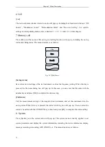
c) Test steps
1) As shown in the figure, connect the test instrument, turn on it and warm it up for 30min.
2) Open the RF source window by pressing the [Receiver] hard key or pressing the [Measurement]
hard key and setting the instrument menu. Set RF Source 1 as follows.
Port: ANT
Frequency: 1000MHz;
Power: -5 dBm
RF Source 1: ON
3) Set the spectrum analyzer as follows.
Center frequency: 1000MHz
Sweep width: 50kHz
Reference level: 0dBm.
4) Test the SSB phase noise at the deviation of 20kHz according to the standard frequency, and
record the test result into Table A.4.
5) Close RF Source 1 of the test instrument, and set RF Source 2 as follows.
Port: ANT
Frequency: 400MHz;
Power: -5 dBm
RF Source 2: ON
6) Change the center frequency of the spectrum analyzer into 400MHz, and record the test result
of SSB phase noise of RF Source 2 into Table A.4.
4. Parasitic harmonics of RF source
a) Test items
Harmonics is generated arsing from nonlinear signal distortion, and the harmonic frequency is
integer times of the signal carrier frequency.
Harmonics of the signal source of this instrument: ≤-30dBc.
b) Test block diagram and meters
The same output power range and accuracy test.
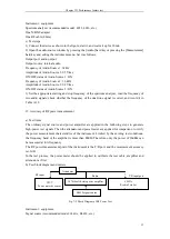
c) Test steps
1) As shown in the figure, connect the test instrument, turn on it and warm it up for 30min.
Summary of Contents for 4992A
Page 1: ...I 4992A Radio Test Set User Manual China Electronics Technology Instruments Co Ltd...
Page 2: ......
Page 5: ......
Page 6: ......
Page 7: ......
Page 23: ...Article I Handling Instructions 11 Article I Handling Instructions...
Page 93: ...81 Article II Technical Specifications...
Page 132: ...Article III Maintenance Instructions 120 Article III Maintenance Instructions...


