


Chapter VII Performance feature test
112
sweep width: 998MHz
Test type: SWR
3) Press the [Calibration] soft key, click “Start calibration”, and connect the open circuit, short
circuit and matching calibration kit in sequence to the SWR port according to the prompts, and
complete calibration. Click “Calibration Done”, and save the calibration data.
4) After calibration, connect the SWR port with the 25Ω air line, and apply the matching load at
the end.
5) Set the vertical-axis bottom value of the display as 1 and the top value as 11.
6) With reference to Table A.30, measure the standing wave ratio of each point with the cursor
function, and record the results in the test result table A.30.
B. Measurement accuracy of distance-to-fault (DTF) measurement
a) Test items
The DTF measurement accuracy reflects the DTF accuracy of the whole instrument. In this test,
the cable of the known material and length is measured to locate breaking points.
The indicator requirement is ±10%
b) Test block diagram and meters
Instrument / equipment:
N type calibration kit(recommended model: 31101)
Standard test cable: 4m
c) Test steps
1) Turn on the instrument for 30min warm-up.
2) Open the cable test window of the tested device by pressing the [Cable] hard key or pressing
the [Measurement] hard key and setting the instrument menu. Click this window, and the cable
test menu will pop up in the right side. Set it as follows:
Frequency setting: center frequency: 501MHz
sweep width: 998MHz
Test type: DTF
DTF test: rate: 0.77
Display setting: 0 as the vertical-axis top value and 50 as the bottom value.
3) Press the [Calibration] soft key, click “Start calibration”, and connect the open circuit, short
circuit and matching calibration kit in sequence to the SWR port according to the prompts, and
complete calibration. Click “Calibration Done”, and save the calibration data.
4) After calibration, connect the SWR port with the 4m long test cable, and apply the open-circuit
load on the cable end.
5) Measure the distance of fault points (maximum reflection peak) with the cursor function, and
record the results in the test result record table A.30.
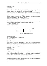
Fig. 7-15 Connection Diagram of DTF Test
SWR port
Open-circuit
load
4992A
Rradio Test Set
Tested cable
Summary of Contents for 4992A
Page 1: ...I 4992A Radio Test Set User Manual China Electronics Technology Instruments Co Ltd...
Page 2: ......
Page 5: ......
Page 6: ......
Page 7: ......
Page 23: ...Article I Handling Instructions 11 Article I Handling Instructions...
Page 93: ...81 Article II Technical Specifications...
Page 132: ...Article III Maintenance Instructions 120 Article III Maintenance Instructions...


