


Chapter IV Operation Guidance
50
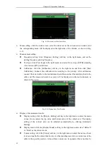
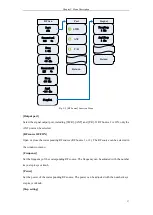
The audio meter should be subject to zero calibration before the test. Fig. 4-29 shows the audio
meter display window. Click “Zero Calibration” on the touch screen or the [Zero Calibration] soft
key in the right side for zero calibration of the audio meter. Note that all connections should be
disconnected before zero calibration.
Display of measurement results:
The averaging of measurement results can be set according to the stability requirements. In
the audio meter display window shown in Fig. 4-29, click the [Average] soft key in the right
side of the touch screen, and open
“
Average
”
. Then click the [Averaging Times] key in the
right menu of the touch screen, and the measurement result will be displayed after averaging
according to the set times.
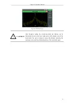
Click the [Voltage Unit] soft key in the right menu of the touch screen, and select the output
unit: V, mV, dBuV, dBm, W, etc. Note that if the display unit is power, the output power will
be calculated according to the matching impedance of the system.
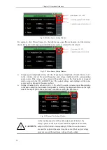
The distortion type of the measurement can be set according to the requirements of signal
distortion measurement results. Click the [Distortion Type] soft key in the right side of the
touch screen: THD (harmonic distortion) and THD+N (total distortion). The user can select
the distortion type according to the requirements.
Alarm setting: judge whether the measurement result conforms to the requirements. If it is
beyond the range, the alarm color will be displayed to make the judgment more intuitive.
Click
“
Alarm Setting
”
in the window, or click the [Alarm Setting] soft key in the right menu
to open the alarm setting window, and set the upper alarm limit and lower alarm limit. Note
that the alarm setting must be within the measurement range between the upper and lower
limit.
3. Setting of digital voltmeter
The digital voltmeter of 4992A is deigned for AC or DC voltage measurement of DVM input
ports. The user can select the coupling mode according to the characteristics of the tested signal,
estimate the level range of the input signal and select the appropriate range.
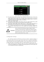
Window opening: open the digital voltmeter window by pressing the [Measurement] hard
key and setting the instrument menu, and press the [Full Screen] soft key in the lower part of
the screen to maximize this window, as shown below.
Fig. 4-32 Digital Voltmeter Display Window
Menu calling: click this touch screen, select the digital voltmeter window, and the relevant
setting menu will pop up in the right side.
Measurement setting:
First select the measurement mode. Click the [Measurement Mode] soft key of the right
menu in the touch screen for port setting, and select the DC or AC mode.
Click the [Range Selection] soft key of the right menu of the touch screen for port setting.
The range setting window of the digital voltmeter is shown in Fig. 4-33. Select the
appropriate range.
Summary of Contents for 4992A
Page 1: ...I 4992A Radio Test Set User Manual China Electronics Technology Instruments Co Ltd...
Page 2: ......
Page 5: ......
Page 6: ......
Page 7: ......
Page 23: ...Article I Handling Instructions 11 Article I Handling Instructions...
Page 93: ...81 Article II Technical Specifications...
Page 132: ...Article III Maintenance Instructions 120 Article III Maintenance Instructions...


