


Chapter VII Performance feature test
110
Impedance: High Z
3) Open the oscilloscope window of the tested device by pressing the [Measurement] hard key and
setting the instrument menu, and set it as follows:
Time/interval: 1ms
Amplitude/interval: 100mV
Reference position: 4
Trigger: trigger mode: normal
Pules edge: rising
Trigger level: 0V
Trigger position: 0nS
Port setting: external audio
External audio setting: impedance: high impedance
Range: 0.1V to 3V
Enable the oscilloscope cursor function, measure the amplitude of the input signal, and record the
results in the test record table A.28.
4) Set the amplitude of the AC sine signal of the function generator according to the table,
properly adjust the vertical-axis display setting of the oscilloscope, measure the amplitude of the
input signal with the cursor function of the oscilloscope, and record the results in the test record
table A.28.
5) Then test the measurement accuracy of the AC input signal of DVM, and change the
oscilloscope input setting as follows:
Port setting: DVM
DVM setting: coupling mode: AC
Range: 0.1V to 3V
6) Repeat Step 4) and record the results in the test record table A.28.
7) Then test the measurement accuracy of the DC input signal of DVM, and change the DC
output signal of the function generator.
8) Based on Step 5), and change the oscilloscope input setting as follows:
DVM setting: coupling mode: DC
9) Set the amplitude of the DC output signal of the function generator according to the table,
properly adjust the vertical-axis display setting of the oscilloscope, measure the amplitude of the
input signal with the cursor function of the oscilloscope, and record the results in the test record
table A.28.
B. Horizontal measurement accuracy
a) Test items
The output pulse width of the function generator is applied as the benchmark to test the
△
t
measurement accuracy of the oscilloscope, i.e. the horizontal time measurement accuracy. The
requirement of this indicator is ±3%.
b) Test block diagram and meters
The test block diagram and meters are the same as those in the vertical measurement accuracy test
of the oscilloscope.
c) Test steps
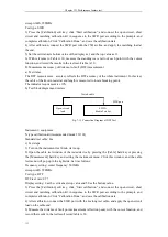
1) Complete the test connection as shown in the figure, start the instrument and warm it up for
30min.
Summary of Contents for 4992A
Page 1: ...I 4992A Radio Test Set User Manual China Electronics Technology Instruments Co Ltd...
Page 2: ......
Page 5: ......
Page 6: ......
Page 7: ......
Page 23: ...Article I Handling Instructions 11 Article I Handling Instructions...
Page 93: ...81 Article II Technical Specifications...
Page 132: ...Article III Maintenance Instructions 120 Article III Maintenance Instructions...


