


Chapter IV Operation Guidance
44
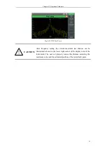
CAUTION:
Note that the speed factor and cable loss are inherent parameters
of the cable. In case of any ambiguity, consult the cable
specifications or cable manufacturer. The user cannot manually
set the speed factor, unit loss, etc. until “User” is set under
[Cable Type].
Setting of length estimate: after the frequency range is set, the distance estimate will be
set automatically. In order to facilitate observation, the length estimate can be reduced
properly within this range.
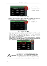
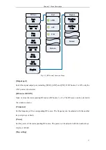
Fig. 4-21 Cable Type Calling Interface
Calibration: click the [Calibration] soft key in the right menu and then click [Start
Calibration]. Connect the calibration kit according to the prompt. After calibration, connect
the tested cable to the test instrument. If only the length of the tested intact cable needs to be
estimated, connect the open-circuit or short-circuit device (as the fault point) to the terminal
of the tested cable to provide the obvious peak point for reading of the cable length.
Display of measurement results:
Display setting: click the [Display Setting] soft key in the right menu to enter the menu of
next level, and set the top value and bottom value of the vertical axis. The display setting of
the vertical axis can be adjusted automatically by clicking [Automatic Setting].
Display mode: click the [Display Mode] soft key in the right menu and select “isplay m or
“or la as the current mode.
Cursor setting: click the [Cursor] soft key in the right menu to enter the menu of next level,
and enable the cursor function to view the standing wave ratio or return loss of the cable in
the specific position. At most three cursors can be opened at the same time by [ON OFF]
setting. The cursor can be dragged into the ideal position by selecting the [Position] soft key,
or rapidly positioned by directly selecting the [Peak], [Left Peak] or [Right Peak]. The
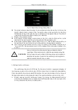
normal or differential mode can be selected with the [Mode] soft key. In DTF measurement,
the cursor is generally positioned at the peak (i.e. fault point) so as to read the position of the
fault point, i.e. the distance between the fault point and the measurement point of the test
instrument. The measured fault point position is shown in Fig. 4-22.
!
Summary of Contents for 4992A
Page 1: ...I 4992A Radio Test Set User Manual China Electronics Technology Instruments Co Ltd...
Page 2: ......
Page 5: ......
Page 6: ......
Page 7: ......
Page 23: ...Article I Handling Instructions 11 Article I Handling Instructions...
Page 93: ...81 Article II Technical Specifications...
Page 132: ...Article III Maintenance Instructions 120 Article III Maintenance Instructions...


